Kia Rio: Hydraulic System / Line Pressure Control Solenoid Valve
Specifications
| Specification |
|
Item |
Specification |
|
Type |
Normal open |
|
Input voltage |
12 V |
|
Coil resistance |
3.5 ± 0.2 Ω (at 25°C, 77°F) |
|
Frequency |
400 - 1000 Hz |
Components and components location
| Component Location |
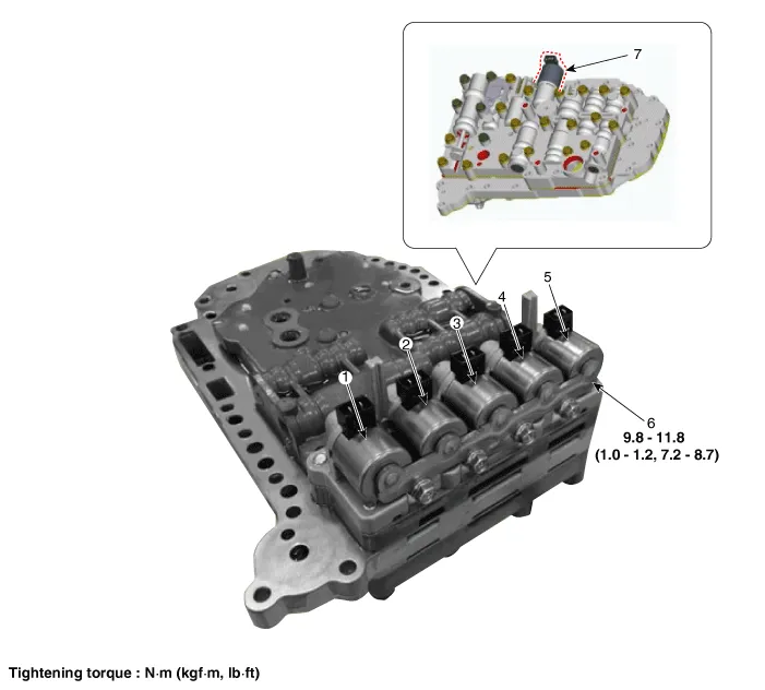
| 1. Overdrive clutch control solenoid
valve (PCSV-A) 2. ON/OFF solenoid valve (SCSV-A) 3. Torque converter control solenoid valve (PCSV-D) 4. Underdrive clutch control solenoid valve (PCSV-C) |
5. 24 brake control solenoid
valve (PCSV-B) 6. Solenoid valve support bracket 7. Line pressure control solenoid valve (LINE_VFS) |
Description and operation
| Description |
| • |
Line pressure control solenoid valve is a VFS (Variable Force Solenoid) type. |
| • |
When TCM supplies variable current to solenoid valve, line pressure is controlled by solenoid valve. |
Schematic diagrams
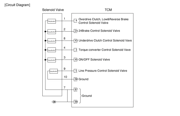
| Circuit Diagram |
Repair procedures
| Inspection |
| 1. |
Switch "OFF" ignition. |
| 2. |
Remove the air cleaner. (Refer to Engine Mechanical System - "Air cleaner") |
| 3. |
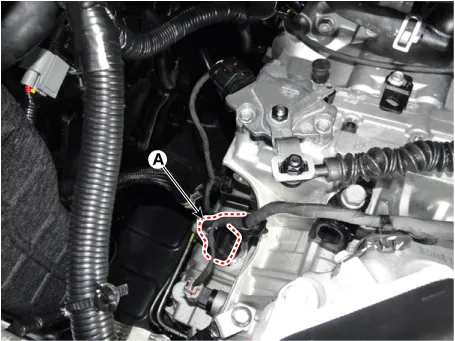
Disconnect the main connector (A).
|
| 4. |
Measure the resistance between ground terminal (10) and signal terminal (9).
|
| Removal |
| 1. |
Remove the valve body assembly. (Refer to Hydraulic System - "Valve Body") |
| 2. |
Disconnect the solenoid valve connector. |
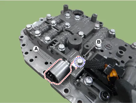
| 3. |
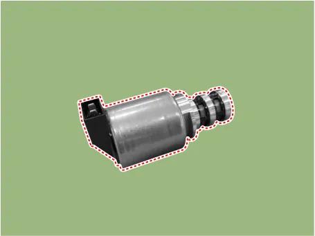
Remove the line pressure control solenoid valve (A) after removing the support bracket by loosening a bolt (B).
|
| Installation |
| 1. |
Install in the reverse order of removal.
|

Specifications Specification Item Specification Type Normal open Input voltage 12 V Coil resistance 3.
Specifications Specification Item Specification Type Normal open Input voltage 12 V Coil resistance 3.
Other information:
Kia Rio 2017-2023 YB Service Manual: Ignition Switch
Repair procedures Inspection 1. Disconnect the key warning switch connector (A) and ignition switch connector (B) from the steering column. 2. Check for continuity between the terminals.
Kia Rio 2017-2023 YB Service Manual: Rheostat
Components and components location Components Repair procedures Removal 1. Disconnect the negative (-) battery terminal. 2. Remove the crash pad lower panel. (Refer to Body - "Crash Pad Lower Panel") 3.
Categories
- Manuals Home
- Kia Rio Owners Manual
- Kia Rio Service Manual
- Emission Control System
- Timing Chain
- Maintenance Schedule
- New on site
- Most important about car
