Kia Rio: Engine Control System / Manifold Absolute Pressure Sensor (MAPS)
Specifications
| Specification |
Manifold Absolute Pressure Sensor (MAPS)
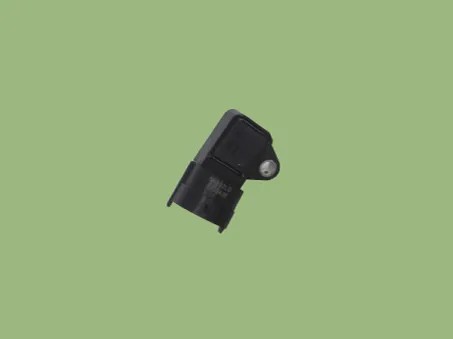
▷ Type: Piezo-resistive pressure sensor type
|
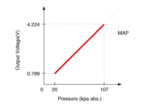
Pressure [kPa (kgf/cm², psi)] |
Output Voltage (V) [Vref = 5V] |
|
20.0 (0.20, 2.9) |
0.79 |
|
46.7 (0.47, 6.77) |
1.84 |
|
101.32 (1.03, 14.7) |
4.0 |
Description and operation
| Description |
Manifold Absolute Pressure Sensor (MAPS) is a speed-density type sensor and is installed on the surge tank. It senses absolute pressure of the surge tank and transfers the analog signal proportional to the pressure to the ECM. By using this signal, the ECM calculates the intake air quantity and engine speed.
The MAPS consists of a piezo-electric element and a hybrid IC amplifying the element output signal. The element is silicon diaphragm type and adapts pressure sensitive variable resistor effect of semi-conductor. Because 100% vacuum and the manifold pressure apply to both sides of the sensor respectively, this sensor can output analog signal by using the silicon variation proportional to pressure change.
Schematic diagrams
| Circuit Diagram |

Repair procedures
| Inspection |
| 1. |
Connect a KDS/GDS on Data Link Connector (DLC). |
| 2. |
Check MAPS output voltage at idle and IG ON.
|
| Removal |
| 1. |
Turn ignition switch OFF and disconnect the battery negative (-) terminal. |
| 2. |
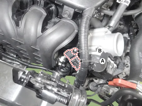
Disconnect the manifold absolute pressure sensor connector (A). |
| 3. |
Remove the installation screw (B), and then remove the sensor from the surge tank.
|
| Installation |
|

| 1. |
Installation is reverse of removal. |
Troubleshooting
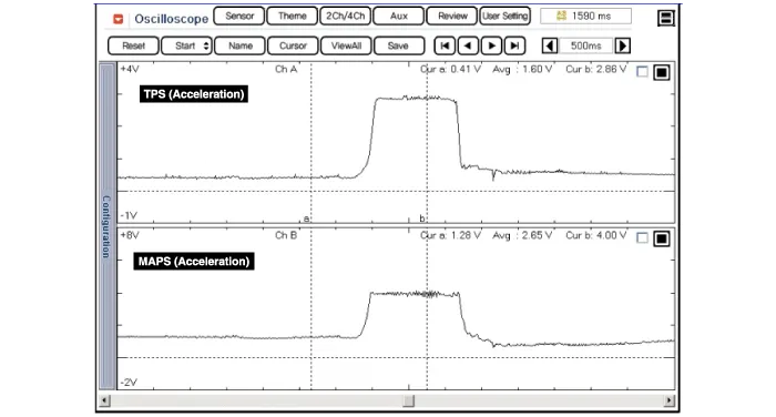
| Waveform |
Specifications Specification ETC Module Throttle Position Sensor (TPS) [integrated into ETC Module] ▷ Type: Hall IC Non-contact sensor type ▷ Specification Throttle angle(°) Output Voltage (V) [Vref=5V] TPS1 TPS2 0 0.
Specifications Specification Intake Air Temperature Sensor (IATS) ▷ Type: Thermistor type Temperature Resistance (kΩ) °C °F -40 -40 40.
Other information:
Kia Rio 2017-2023 YB Service Manual: Overhead Console Lamp
Repair procedures Inspection 1. Remove the overhead console lamp assembly then check for continuity between terminals. If the continuity is not as specified, replace the map lamp switch. Removal 1.
Kia Rio 2017-2023 YB Service Manual: Air Conditioning System
General safety information and caution Instructions When Handling Refrigerant 1. R-134a liquid refrigerant is highly volatile. A drop on the skin of your hand could result in localized frostbite. When handling the refrigerant, be sure to wear gloves.
Categories
- Manuals Home
- Kia Rio Owners Manual
- Kia Rio Service Manual
- Coolant
- Body (Interior and Exterior)
- Motor Driven Power Steering
- New on site
- Most important about car
