Kia Rio: Engine Control System / Intake Air Temperature Sensor (IATS)
Specifications
| Specification |
Intake Air Temperature Sensor (IATS)
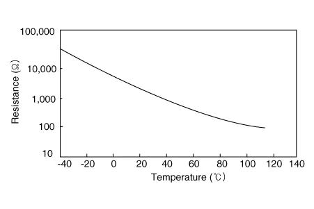
▷ Type: Thermistor type
|
Temperature |
Resistance (kΩ) |
|
|
°C |
°F |
|
|
-40 |
-40 |
40.93 - 48.35 |
|
-30 |
-22 |
23.43 - 27.34 |
|
-20 |
-4 |
13.89 - 16.03 |
|
-10 |
14 |
8.5 - 9.7 |
|
0 |
32 |
5.38 - 6.09 |
|
10 |
50 |
3.48 - 3.90 |
|
20 |
68 |
2.31 - 2.57 |
|
30 |
86 |
1.9 - 2.1 |
|
40 |
104 |
1.08 - 1.21 |
|
50 |
122 |
0.76 - 0.85 |
|
60 |
140 |
0.54 - 0.62 |
|
70 |
158 |
0.40 - 0.45 |
|
80 |
176 |
0.29 - 0.34 |
|
90 |
194 |
0.22 - 0.26 |
|
100 |
212 |
0.17 - 0.20 |
|
110 |
230 |
0.13 - 0.15 |
|
120 |
248 |
0.10 - 0.12 |
|
130 |
266 |
0.08 - 0.09 |
Description and operation
| Description |
Intake Air Temperature Sensor (IATS) is included inside Manifold Absolute Pressure Sensor and detects the intake air temperature.
To calculate precise air quantity, correction of the air temperature is needed because air density varies according to the temperature. So the ECM uses not only MAPS signal but also IATS signal. This sensor has a Negative Temperature Coefficient (NTC) and its resistance is in inverse proportion to the temperature.

Schematic diagrams
| Circuit Diagram |

Repair procedures
| Inspection |
| 1. |
Turn ignition switch OFF. |
| 2. |
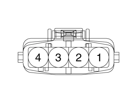
Disconnect IATS connector. |
| 3. |
Measure resistance between IATS terminals 3 and 4. |
| 4. |
Check that the resistance is within the specification.
|
|||||||||||||||||||||||||||||||||||||||||||||||||||||||||||
| Removal |
| 1. |
Turn ignition switch OFF and disconnect the battery negative (-) terminal. |
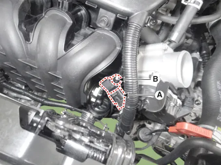
| 2. |
Disconnect the manifold absolute pressure sensor connector (A). |
| 3. |
Remove the installation screw (B), and then remove the sensor from the surge tank.
|
| Installation |
|

| 1. |
Installation is reverse of removal. |
Troubleshooting
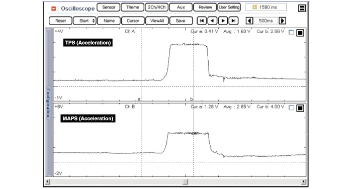
| Waveform |
Specifications Specification Manifold Absolute Pressure Sensor (MAPS) ▷ Type: Piezo-resistive pressure sensor type Pressure [kPa (kgf/cm², psi)] Output Voltage (V) [Vref = 5V] 20.
Specifications Specification Engine Coolant Temperature Sensor (ECTS) ▷ Type: Thermistor type Temperature Resistance (kΩ) °C °F -40 -40 48.
Other information:
Kia Rio 2017-2023 YB Service Manual: Ignition Switch
Repair procedures Inspection 1. Disconnect the key warning switch connector (A) and ignition switch connector (B) from the steering column. 2. Check for continuity between the terminals.
Kia Rio 2017-2023 YB Service Manual: A/C Pressure Transducer
Description and operation Description The A/C Pressure Transducer (APT) convert the pressure value of high pressure line into voltage value after measure it. By converted voltage value, engine ECU controls cooling fan by operating it high speed or low speed.
Categories
- Manuals Home
- Kia Rio Owners Manual
- Kia Rio Service Manual
- Motor Driven Power Steering
- Cooling System
- Suspension System
- New on site
- Most important about car
