Kia Rio: Engine Control System / ETC (Electronic Throttle Control) System
Specifications
| Specification |
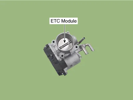
ETC Module
Throttle Position Sensor (TPS) [integrated into ETC Module]
▷ Type: Hall IC Non-contact sensor type
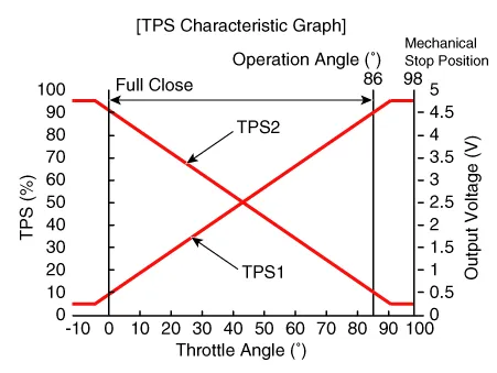
▷ Specification
|
Throttle angle(°) |
Output Voltage (V) [Vref=5V] |
|
|
TPS1 |
TPS2 |
|
|
0 |
0.5 |
4.5 |
|
10 |
0.96 |
4.05 |
|
20 |
1.41 |
3.59 |
|
30 |
1.87 |
3.14 |
|
40 |
2.32 |
2.68 |
|
50 |
2.78 |
2.23 |
|
60 |
3.23 |
1.77 |
|
70 |
3.69 |
1.32 |
|
80 |
4.14 |
0.86 |
|
90 |
4.6 |
0.41 |
|
98 |
4.65 |
0.35 |
|
C.T (0) |
0.5 |
4.5 |
|
W.O.T (86) |
4.41 |
0.59 |
DC Motor [integrated into ETC module]
|
Item |
Specification |
|
Coil Resistance (Ω) |
0.3 - 100 [20°C(68°F)] |
Description and operation
| Description |
The Electronic Throttle Control (ETC) System consists of a throttle body with an integrated control motor and throttle position sensor (TPS). Instead of the traditional throttle cable, an Accelerator Position Sensor (APS) is used to receive driver input. The ECM uses the APS signal to calculate the target throttle angle; the position of the throttle is then adjusted via ECM control of the ETC motor. The TPS signal is used to provide feedback regarding throttle position to the ECM. Using ETC, precise control over throttle position is possible; the need for external cruise control modules/cables is eliminated.
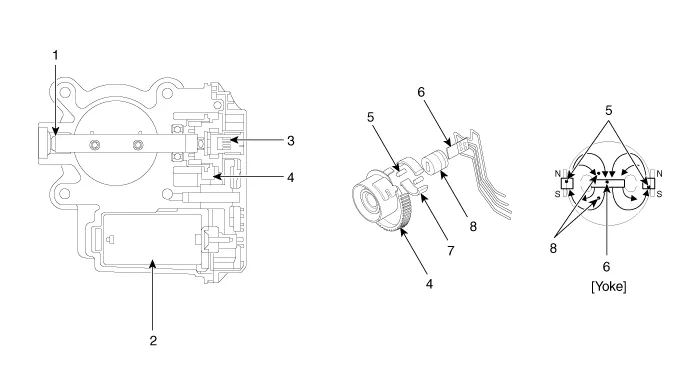
| 1. Dry bearing 2. DC motor 3. Non-contact hall sensor 4. Gear |
5. Magnet 6. Hall IC 7. Yoke 8. Stator |
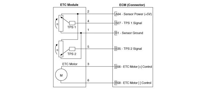
| Schematic Diagram |
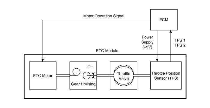
Schematic diagrams
| Circuit Diagram |
Repair procedures
| Inspection |
Throttle Position Sensor (TPS)
| 1. |
Connect the KDS/GDS on the Data Link Connector (DLC). |
| 2. |
Start the engine and measure the output voltage of TPS 1 and 2 at C.T. and W.O.T. [Throttle Position Sensor (TPS)]
|
||||||||||||||||||||||||||||||||||||||||||||
ETC Motor
| 1. |
Switch "OFF" the ignition. |
| 2. |
Disconnect the ETC module connector. |
| 3. |
Measure resistance between the ETC module terminals 1 and 2. |
| 4. |
Check that the resistance is within the specification.
|
| Removal |
| 1. |
Turn ignition switch OFF and disconnect the battery negative (-) terminal. |
| 2. |
Remove the air cleaner assembly. (Refer to Intake And Exhaust System - "Air Cleaner") |
| 3. |
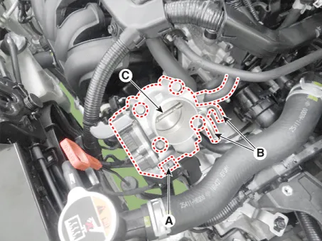
Disconnect the ETC module connector (A). |
| 4. |
Disconnect the vapor hose (B). |
| 5. |
Remove the installation bolts, and then remove the ETC module (C) from the engine.
|
| Installation |
|

| 1. |
Installation is reverse of removal. |
| Adjustment |
| ETC module learning procedure |
Be sure to perform the ETC module learning procedure when replacing or reinstalling the ETC module.
| 1. |
Wait for 1 minute with the ignition switch ON. |
| 2. |
Start the engine and keep it idle for 15 minutes. |
| 3. |
Waif for 1 minute with the ignition switch OFF. |
| 4. |
Restart the engine, and check that the idle speed is stable.
|
Troubleshooting
| Fail-Safe Mode |
|
Item |
Fail-Safe |
|
|
ETC Motor |
Throttle valve stuck at 5° |
|
|
TPS |
TPS 1 fault |
ECM looks at TPS2 |
|
TPS 2 fault |
ECM looks at TPS1 |
|
|
TPS 1,2 fault |
Throttle valve stuck at 5° |
|
|
APS |
APS 1 fault |
ECM looks at APS 2 |
|
APS 2 fault |
ECM looks at APS 1 |
|
|
APS 1,2 fault |
Throttle valve stuck at 5° |
|
When throttle value is stuck at 5°, engine speed is limited at below 1,500rpm and vehicle speed at maximum 40 ~ 50 km/h (25 ~ 31 mph) |
Schematic diagrams Engine Control Module (ECM) Harness Connector Terminal Function [M/T] Connector [A] Pin No.
Specifications Specification Manifold Absolute Pressure Sensor (MAPS) ▷ Type: Piezo-resistive pressure sensor type Pressure [kPa (kgf/cm², psi)] Output Voltage (V) [Vref = 5V] 20.
Other information:
Kia Rio 2017-2023 YB Service Manual: Lane Departure Warning System (LDWS)
Components and components location Components 1. LDWS ON/OFF switch 2. Instrument cluster 3. LDWS unit (MFC) ※ MFC : Multi Function Camera – Function : LDWS, HBA, AEB Description and operation Description System block diagram Components of LDWS
Kia Rio 2017-2023 YB Service Manual: Heater & A/C Control Unit (FATC)
Components and components location Components Connector Pin Function No. Connector A Connector B 1 Battery ⁻ 2 ISG battery (+) ⁻ 3 Illumination (+) ⁻
Categories
- Manuals Home
- Kia Rio Owners Manual
- Kia Rio Service Manual
- Maintenance Schedule
- Motor Driven Power Steering
- Cooling System
- New on site
- Most important about car
