Kia Rio: Engine Control System / Engine Control Module (ECM)
Schematic diagrams
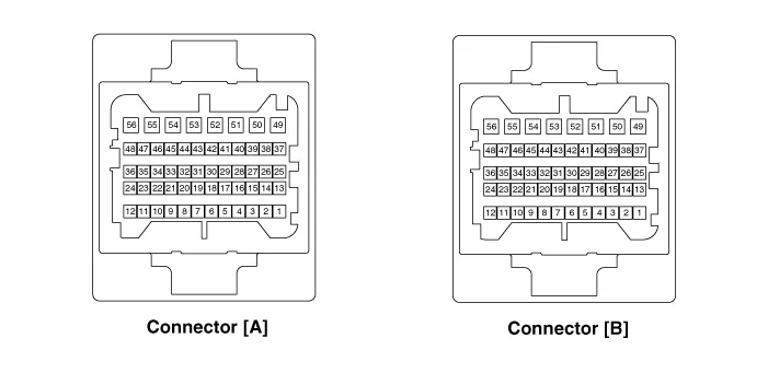
| Engine Control Module (ECM) |
| Harness Connector |
| Terminal Function [M/T] |
Connector [A]
|
Pin No. |
Description |
Connected to |
|
1 |
Ignition coil (Cylinder #1) control output |
Ignition coil (Cylinder #1) |
|
2 |
Ignition coil (Cylinder #4) control output |
Ignition coil (Cylinder #4) |
|
3 |
Ignition coil (Cylinder #2) control output |
Ignition coil (Cylinder #2) |
|
4 |
Purge Control Solenoid Valve control output |
Purge Control Solenoid Valve (PCSV) |
|
5 |
Ignition coil (Cylinder #3) control output |
Ignition coil (Cylinder #3) |
|
6 |
Injector (Cylinder #2) control output |
Injector (Cylinder #2) |
|
7 |
Injector (Cylinder #1) control output |
Injector (Cylinder #1) |
|
8 |
Heated Oxygen Sensor [Bank 1/ Sensor 2] Heater control output |
Heated Oxygen Sensor [Bank 1/ Sensor 2] |
|
9 |
Injector (Cylinder #4) control output |
Injector (Cylinder #4) |
|
10 |
Heated Oxygen Sensor [Bank 1/ Sensor 1] Heater control output |
Heated Oxygen Sensor [Bank 1/ Sensor 1] |
|
11 |
- |
|
|
12 |
- |
|
|
13 |
Camshaft Position Sensor (CMPS) [Bank 1/Exhaust] signal input |
Camshaft Position Sensor (CMPS) [Bank 1/Exhaust] |
|
14 |
- |
|
|
15 |
Sensor ground |
Brake booster vacuum pressure sensor (BBVPS) [With ISG] |
|
16 |
- |
|
|
17 |
Sensor ground |
Engine coolant temperature sensor (ECTS) |
|
18 |
Sensor ground |
Manifold absolute pressure sensor (MAPS) |
|
19 |
- |
|
|
20 |
Cooling Fan Relay [High] control output |
Cooling Fan Relay [High] |
|
21 |
Engine RPM signal output |
Smart key Control Module |
|
22 |
- |
|
|
23 |
Camshaft Position Sensor (CMPS) [Bank 1/Intake] signal input |
haft Position Sensor (CMPS) [Bank 1/Intake] |
|
24 |
Brake booster vacuum pressure sensor signal input |
Brake booster vacuum pressure sensor (BBVPS) [With ISG] |
|
25 |
- |
|
|
26 |
Engine coolant temperature sensor (ECTS) signal input |
Engine coolant temperature sensor (ECTS) |
|
27 |
Manifold absolute pressure sensor (MAPS) signal input |
Manifold absolute pressure sensor (MAPS) |
|
28 |
Sensor ground |
Heated Oxygen Sensor (HO2S) [Bank 1/Sensor 2] |
|
29 |
Vehicle speed signal input |
ABS/ESP Control Module [With ABS/ESP] |
|
30 |
- |
|
|
31 |
Electric Load signal input (Defrost) |
A/C Control Module, Outside Mirror |
|
32 |
Alternator [FR] signal input |
Alternator |
|
33 |
Heated Oxygen Sensor [Bank 1/ Sensor 2] signal input |
Heated Oxygen Sensor [Bank 1/ Sensor 2] |
|
34 |
Sensor ground |
Heated Oxygen Sensor [Bank 1/ Sensor 1] |
|
35 |
- |
|
|
36 |
Heated Oxygen Sensor [Bank 1/ Sensor 1] signal input |
Heated Oxygen Sensor [Bank 1/ Sensor 1] |
|
37 |
- |
|
|
38 |
Injector (Cylinder #3) control output |
Injector (Cylinder #3) |
|
39 |
- |
|
|
40 |
- |
|
|
41 |
Brake Lamp Switch signal input |
Brake Switch |
|
42 |
- |
|
|
43 |
ISG OFF switch signal input |
ISG OFF switch |
|
44 |
- |
|
|
45 |
- |
|
|
46 |
- |
|
|
47 |
Battery voltage supply after ignition switch |
Ignition Switch |
|
48 |
ISG OFF switch indicator control |
ISG OFF switch |
|
49 |
Immobilizer communication line |
Immobilizer Control module [Without Smart Key] |
|
Smart Key Control module [With Smart Key] |
||
|
50 |
- |
|
|
51 |
- |
|
|
52 |
Fuel Pump Relay control output (Without smart key) |
Fuel Pump Relay |
|
53 |
- |
|
|
54 |
Neutral switch signal input |
Neutral switch |
|
55 |
Sensor power (+5V) |
Manifold absolute pressure sensor (MAPS) |
|
56 |
Start relay control output (With smart key) |
Start relay |
|
57 |
C-CAN [Low] |
Other control module, Data Link Connector (DLC), |
|
58 |
C-CAN [High] |
Other control module, Data Link Connector (DLC), |
|
59 |
Sensor ground |
Crankshaft Position Sensor (CKPS) |
|
60 |
Crankshaft Position Sensor (CKPS) signal input |
Crankshaft Position Sensor (CKPS) |
|
61 |
Main Relay control output |
Main Relay |
|
62 |
Cooling Fan Relay [Low] control output |
Cooling Fan Relay [Low] |
|
63 |
Alternator [COM] control output |
Alternator |
|
64 |
Sensor power (+5V) |
Throttle Position Sensor (TPS) # 1, 2 [ETC module] |
|
65 |
- |
|
|
66 |
- |
|
|
67 |
- |
|
|
68 |
- |
|
|
69 |
Power Ground |
Chassis Ground |
|
70 |
Power Ground |
Chassis Ground |
|
71 |
Power Ground |
Chassis Ground |
|
72 |
Battery voltage supply after main relay |
Main relay |
|
73 |
- |
|
|
74 |
Battery voltage supply after main relay |
Main Relay |
Connector [B]
|
Pin No. |
Description |
Connected to |
|
1 |
Sensor ground |
Throttle Position Sensor (TPS) 1, 2 |
|
2 |
- |
|
|
3 |
- |
|
|
4 |
- |
|
|
5 |
Sensor ground |
A/C Pressure Transducer (APT) |
|
6 |
- |
|
|
7 |
- |
|
|
8 |
- |
|
|
9 |
- |
|
|
10 |
- |
|
|
11 |
A/C Pressure Transducer (APT) signal input |
A/C Pressure Transducer (APT) |
|
12 |
Sensor ground |
Accelerator Position Sensor (APS) 2 |
|
13 |
- |
|
|
14 |
- |
|
|
15 |
- |
|
|
16 |
Brake switch 1 signal input |
Brake lamp swtich , Brake switch |
|
17 |
- |
|
|
18 |
Accelerator Position Sensor (APS) #2 signal input |
Accelerator Position Sensor (APS) #2 |
|
19 |
- |
|
|
20 |
Sensor ground |
Accelerator Position Sensor (APS) 1 |
|
21 |
- |
|
|
22 |
Sensor ground |
Camshaft Position Sensor (CMPS) [Bank 1/Intake] |
|
23 |
Camshaft Position Sensor (CMPS) [Bank 1/Exhaust] |
|
|
24 |
- |
|
|
25 |
Sensor power (+5V) |
Accelerator Position Sensor (APS) #2 |
|
A/C Pressure Transducer (APT) |
||
|
Camshaft Position Sensor (CMPS) [Bank 1/Exhaust] |
||
|
26 |
- |
|
|
27 |
Throttle position sensor (TPS) #1 signal input |
Throttle position sensor (TPS) #1 |
|
28 |
- |
|
|
29 |
Accelerator Position Sensor (APS) #1 signal input |
Accelerator Position Sensor (APS) #1 |
|
30 |
Start switch signal input |
Ignition switch |
|
31 |
Clutch Switch signal input |
Clutch switch [M.T] |
|
32 |
- |
|
|
33 |
Sensor power (+5V) |
Accelerator Position Sensor (APS) 1 |
|
Crankshaft Position Sensor (CKPS) [With ISG] |
||
|
Brake booster vacuum pressure sensor (BBVPS) [With ISG] |
||
|
Camshaft Position Sensor (CMPS) [Bank 1/Intake] |
||
|
34 |
- |
|
|
35 |
Throttle position sensor (TPS) #2 signal input |
Throttle position sensor (TPS) #2 [ETC module] |
|
36 |
Intake air temperature sensor (IATS) signal input |
Intake Air temperature sensor (IATS) |
|
37 |
- |
|
|
38 |
- |
|
|
39 |
- |
|
|
40 |
Variable Intake Solenoid (VIS) Valve control output |
Variable Intake Solenoid (VIS) Valve |
|
41 |
Knock sensor (KS) signal input |
Knock sensor (KS) |
|
42 |
Sensor ground |
Knock sensor (KS) |
|
43 |
LIN communication signal input |
Battery Sensor |
|
44 |
- |
|
|
45 |
- |
|
|
46 |
- |
|
|
47 |
- |
|
|
48 |
- |
|
|
49 |
- |
|
|
50 |
- |
|
|
51 |
- |
|
|
52 |
- |
|
|
53 |
Fuel Pump Relay control output (With smart key) |
Fuel Pump Relay |
|
54 |
- |
|
|
55 |
CVVT Oil Control (OCV) Valve [Bank 1/Intake] control output |
CVVT Oil Control Valve (OCV) [Bank 1/Intake] |
|
56 |
ETC motor (+) control output |
ETC Module |
|
57 |
CVVT Oil Control (OCV) Valve [Bank 1/Exhaust] control output |
CVVT Oil Control Valve (OCV) [Bank 1/Exhaust] |
|
58 |
ETC motor (-) control output |
ETC Module |
| Terminal input/output signal [M/T] |
Connector [A]
|
Pin No. |
Description |
Condition |
Type |
Level |
|
1 |
Ignition coil (Cylinder #1) control output |
Idle |
Pulse |
1st Voltage: 300 - 400V |
|
ON Voltage: Max. 2.0V |
||||
|
2 |
Ignition coil (Cylinder #4) control output |
Idle |
Pulse |
1st Voltage: 300 - 400V |
|
ON Voltage: Max. 2.0V |
||||
|
3 |
Ignition coil (Cylinder #2) control output |
Idle |
Pulse |
1st Voltage: 300 - 400V |
|
ON Voltage: Max. 2.0V |
||||
|
4 |
Purge Control Solenoid Valve control output |
Active |
Pulse |
Hi: Battery Voltage |
|
Inactive |
Lo: Max. 1.0V |
|||
|
5 |
Ignition coil (Cylinder #3) control output |
Idle |
Pulse |
1st Voltage: 300 - 400V |
|
ON Voltage: Max. 2.0V |
||||
|
6 |
Injector (Cylinder #2) control output |
Idle |
Pulse |
Hi: Battery Voltage |
|
Lo: Max. 1.0V |
||||
|
Vpeak: Max. 80V |
||||
|
7 |
Injector (Cylinder #1) control output |
Idle |
Pulse |
Hi: Battery Voltage |
|
Lo: Max. 1.0V |
||||
|
Vpeak: Max. 80V |
||||
|
8 |
Heated Oxygen Sensor (Bank1/ Sensor 2) Heater control output |
Engine Run |
Pulse |
Hi: Battery Voltage |
|
Lo: Max. 1.0V |
||||
|
9 |
Injector (Cylinder #4) control output |
Idle |
Pulse |
Hi: Battery Voltage |
|
Lo: Max. 1.0V |
||||
|
Vpeak: Max. 80V |
||||
|
10 |
Heated Oxygen Sensor [Bank 1/ Sensor 1] Heater control output |
Engine Run |
Pulse |
Hi: Battery Voltage |
|
Lo: Max. 1.0V |
||||
|
11 |
- |
|
|
|
|
12 |
- |
|
|
|
|
13 |
Camshaft Position Sensor [Bank1/ Exhaust] signal input |
Idle |
Pulse |
Hi: Battery Voltage |
|
Lo: Max. 0.5V |
||||
|
14 |
- |
|
|
|
|
15 |
Sensor ground |
Idle |
DC |
Max. 50mV |
|
16 |
- |
|
|
|
|
17 |
Sensor ground |
Idle |
DC |
Max. 50mV |
|
18 |
Sensor ground |
Idle |
DC |
Max. 50mV |
|
19 |
- |
|
|
|
|
20 |
Cooling fan relay [High] control output |
Relay OFF |
DC |
Battery Voltage |
|
Relay ON |
Max. 1.0V |
|||
|
21 |
Engine speed signal output |
Idle |
Pulse |
Hi: Battery Voltage |
|
Lo: Max. 0.5V |
||||
|
Freq.: 20 - 26Hz |
||||
|
22 |
- |
|
|
|
|
23 |
Camshaft Position Sensor [Bank1/ Intake] signal input |
Idle |
Pulse |
Hi: Battery Voltage |
|
Lo: Max. 0.5V |
||||
|
24 |
Brake booster vacuum pressure sensor signal input |
|
|
|
|
25 |
- |
|
|
|
|
26 |
Engine Coolant Temperature Sensor signal input |
Idle |
Analog |
0.5 - 4.5V |
|
27 |
Manifold Absolute Pressure Sensor signal input |
Idle |
Analog |
0.8 - 1.6V |
|
28 |
Sensor ground |
Racing |
Analog |
Rich: 0.6 - 1.0V |
|
Lean: Max. 0.4V |
||||
|
29 |
Vehicle speed signal input |
Idle |
Pulse |
Hi: Min. 4.5 V |
|
Lo: Max. 1.0 V |
||||
|
Vehicle Run |
Hi: Min. 4.5 V |
|||
|
(30km) |
Lo: Max. 1.0 V |
|||
|
30 |
- |
|
|
|
|
31 |
Electric Load signal input (Defrost) |
|
|
|
|
32 |
Alternator [FR] signal input |
|
|
|
|
33 |
Heated Oxygen Sensor (Bank1/ Sensor 2) signal input |
Racing |
Analog |
Rich: 0.6 - 1.0V |
|
Lean: Max. 0.4V |
||||
|
34 |
Sensor ground |
Idle |
DC |
Max. 50mV |
|
35 |
- |
|
|
|
|
36 |
Heated Oxygen Sensor (Bank1/ Sensor 1) signal input |
Racing |
Analog |
Rich: 0.6 - 1.0V |
|
Lean: Max. 0.4V |
||||
|
37 |
- |
|
|
|
|
38 |
Injector (Cylinder #1) control output |
Idle |
Pulse |
Hi: Battery Voltage |
|
Lo: Max. 1.0V |
||||
|
Vpeak: Max. 80V |
||||
|
39 |
- |
|
|
|
|
40 |
- |
|
|
|
|
41 |
Brake Lamp Switch signal input |
Swtich ON |
DC |
Battery Voltage |
|
Switch OFF |
Max. 1.0V |
|||
|
42 |
- |
|
|
|
|
43 |
ISG OFF switch signal input |
|
|
|
|
44 |
- |
|
|
|
|
45 |
- |
|
|
|
|
46 |
- |
|
|
|
|
47 |
Battery voltage supply after ignition switch |
IG OFF |
DC |
Max. 1.0V |
|
IG ON |
Battery Voltage |
|||
|
48 |
ISG OFF switch indicator control |
|
48 |
ISG OFF switch indicator control |
|
49 |
Immobilizer communication line |
When communicating after IG ON |
Pulse |
Hi: Min. 8.5V |
|
Lo: Max. 3.5V |
||||
|
50 |
- |
|
|
|
|
51 |
- |
|
|
|
|
52 |
Fuel Pump Relay control output (Without smart key) |
|
|
|
|
53 |
- |
|
|
|
|
54 |
- |
|
|
|
|
55 |
Sensor power (+5V) |
IG OFF |
DC |
Max. 0.5V |
|
IG ON |
4.9 - 5.1V |
|||
|
56 |
Start relay control output (With smart key) |
Relay OFF |
DC |
Battery Voltage |
|
Relay ON |
Max. 1.0V |
|||
|
57 |
C-CAN [LOW] |
RECESSIVE |
Pulse |
2.0 - 3.0V |
|
DOMINANT |
0.5 - 2.25V |
|||
|
58 |
C-CAN [HIGH] |
RECESSIVE |
Pulse |
2.0 - 3.0V |
|
DOMINANT |
2.75 - 4.5V |
|||
|
59 |
Sensor ground |
Idle |
DC |
Max. 50mV |
|
60 |
Crankshaft Position Sensor signal input |
Idle |
SINE |
Vp_p: Min. 1.0V |
|
Wave |
||||
|
61 |
Main Relay control output |
Relay OFF |
DC |
Battery Voltage |
|
Relay ON |
Max. 1.0V |
|||
|
62 |
Cooling Fan Relay [Low] control output |
Relay OFF |
DC |
Battery Voltage |
|
Relay ON |
Max. 1.0V |
|||
|
63 |
Alternator [COM] control output |
|
|
|
|
64 |
Sensor power (+5V) |
IG OFF |
DC |
Max. 0.5V |
|
IG ON |
4.9 - 5.1V |
|||
|
65 |
- |
|
|
|
|
66 |
- |
|
|
|
|
67 |
- |
|
|
|
|
68 |
- |
|
|
|
|
69 |
Power Ground |
Idle |
DC |
Max. 50mV |
|
70 |
Power Ground |
Idle |
DC |
Max. 50mV |
|
71 |
Power Ground |
Idle |
DC |
Max. 50mV |
|
72 |
Battery voltage supply after main relay |
IG OFF |
DC |
Max. 1.0V |
|
IG ON |
Battery Voltage |
|||
|
73 |
- |
|
|
|
|
74 |
Battery voltage supply after main relay |
IG OFF |
DC voltage |
Max. 1.0 V |
|
IG ON |
Battery voltage |
Connector [B]
|
Pin No. |
Description |
Condition |
Type |
Level |
|
1 |
Sensor ground |
Idle |
DC |
Max. 50mV |
|
2 |
- |
|
|
|
|
3 |
- |
|
|
|
|
4 |
- |
|
|
|
|
5 |
Sensor ground |
Idle |
DC |
Max. 50mV |
|
6 |
- |
|
|
|
|
7 |
- |
|
|
|
|
8 |
- |
|
|
|
|
9 |
- |
|
|
|
|
10 |
- |
|
|
|
|
11 |
A/C Pressure Transducer (APT) signal input |
A/C ON |
Analog |
Max. 4.8V |
|
12 |
Sensor ground |
Idle |
DC |
Max. 50mV |
|
13 |
- |
|
|
|
|
14 |
- |
|
|
|
|
15 |
- |
|
|
|
|
16 |
Brake switch 1 signal input |
Brake ON |
DC |
Battery Voltage |
|
Brake OFF |
Max. 1.0V |
|||
|
17 |
- |
|
|
|
|
18 |
Accelerator Position Sensor (APS) #2 signal input |
C.T |
Analog |
0.2 - 0.7V |
|
W.O.T |
1.2 - 2.4V |
|||
|
19 |
- |
|
|
|
|
20 |
Sensor ground |
Idle |
DC |
Max. 50mV |
|
21 |
- |
|
|
|
|
22 |
Sensor ground |
Idle |
DC |
Max. 50mV |
|
23 |
Sensor ground |
Idle |
DC |
Max. 50mV |
|
24 |
- |
|
|
|
|
25 |
Sensor power (+5V) |
IG OFF |
DC |
Max. 0.5V |
|
IG ON |
4.8 - 5.2V |
|||
|
26 |
- |
|
|
|
|
27 |
Throttle Position Sensor (TPS) #1 signal input |
C.T |
Analog |
0.3 - 0.9V |
|
W.O.T |
1.5 - 3.0V |
|||
|
28 |
- |
|
|
|
|
29 |
Accelerator Position Sensor (APS) #1 signal input |
C.T |
Analog |
0.2 - 0.7V |
|
W.O.T |
1.2 - 2.4V |
|||
|
30 |
Start switch signal input |
|
|
|
|
31 |
Clutch switch signal input |
|
|
|
|
32 |
- |
|
|
|
|
33 |
Sensor power (+5V) |
IG OFF |
DC |
Max. 0.5V |
|
IG ON |
4.8 - 5.2V |
|||
|
34 |
- |
|
|
|
|
35 |
Throttle Position Sensor (TPS) #2 signal input |
C.T |
Analog |
4.2 - 5.0V |
|
W.O.T |
3.3 - 3.8V |
|||
|
36 |
Intake Air Temperature Sensor signal input |
Idle |
DC |
0 - 5V |
|
37 |
- |
|
|
|
|
38 |
- |
|
|
|
|
39 |
- |
|
|
|
|
40 |
Variable Intake Solenoid (VIS) Valve control output |
Relay OFF |
DC voltage |
Battery voltage |
|
Relay ON |
Max. 1.65V |
|||
|
41 |
Knock sensor (KS) signal input |
Knocking |
Variable |
|
|
Normal |
Frequency |
|
||
|
42 |
Sensor ground |
Idle |
DC voltage |
Max. 50 mV |
|
43 |
LIN communication signal input |
|
|
|
|
|
|
|||
|
44 |
- |
|
|
|
|
45 |
- |
|
|
|
|
46 |
- |
|
|
|
|
47 |
- |
|
|
|
|
48 |
- |
|
|
|
|
49 |
- |
|
|
|
|
50 |
- |
|
|
|
|
51 |
- |
|
|
|
|
52 |
- |
|
|
|
|
53 |
Fuel Pump Relay control output (With smart key) |
Relay OFF |
DC |
Battery Voltage |
|
Relay ON |
Max. 1.0V |
|||
|
54 |
- |
|
|
|
|
55 |
CVVT Oil Control Valve [Bank1/ Intake] control output |
Idle |
Pulse |
Hi: Battery Voltage |
|
Lo: Max. 1.0V |
||||
|
56 |
ETC motor (+) control output |
Idle |
Pulse |
Hi: Battery Voltage |
|
Lo: Max. 1.0V |
||||
|
57 |
CVVT Oil Control Valve [Bank1/ Exhaust] control output |
Idle |
Pulse |
Hi: Battery Voltage |
|
Lo: Max. 1.0V |
||||
|
58 |
ETC motor (-) control output |
Idle |
Pulse |
Hi: Battery Voltage |
|
Lo: Max. 1.0V |
| Terminal Function [A/T] |
Connector [A]
|
Pin No. |
Description |
Connected to |
|
1 |
CVVT Oil Control (OCV) Valve [Bank 1/Intake] control output |
CVVT Oil Control Valve (OCV) [Bank 1/Intake] |
|
2 |
CVVT Oil Control (OCV) Valve [Bank 1/Exhaust] control output |
CVVT Oil Control Valve (OCV) [Bank 1/Exhaust] |
|
3 |
- |
|
|
4 |
- |
|
|
5 |
- |
|
|
6 |
- |
|
|
7 |
- |
|
|
8 |
- |
|
|
9 |
Sensor ground |
Camshaft Position Sensor (CMPS) [Bank 1/Exhaust] |
|
10 |
Sensor ground |
Camshaft Position Sensor (CMPS) [Bank 1/Intake] |
|
11 |
- |
|
|
12 |
- |
|
|
13 |
- |
|
|
14 |
Sensor ground |
Engine coolant temperature sensor (ECTS) |
|
15 |
- |
|
|
16 |
- |
|
|
17 |
- |
|
|
18 |
- |
|
|
19 |
Sensor ground |
Accelerator Position Sensor (APS) 1 |
|
20 |
- |
|
|
21 |
Sensor ground |
Throttle Position Sensor (TPS) 1, 2 |
|
22 |
- |
|
|
23 |
Fuel Pump Relay control output (With smart key) |
Fuel Pump Relay |
|
24 |
|
|
|
25 |
ETC motor (-) control output |
ETC Module |
|
26 |
Variable Intake Solenoid (VIS) Valve control output |
Variable Intake Solenoid (VIS) Valve |
|
27 |
- |
|
|
28 |
- |
|
|
29 |
- |
|
|
30 |
- |
|
|
31 |
- |
|
|
32 |
- |
|
|
33 |
- |
|
|
34 |
- |
|
|
35 |
- |
|
|
36 |
- |
|
|
37 |
Accelerator Position Sensor (APS) #1 signal input |
Accelerator Position Sensor (APS) #1 |
|
38 |
Manifold absolute pressure sensor (MAPS) signal input |
Manifold absolute pressure sensor (MAPS) |
|
39 |
Engine coolant temperature sensor (ECTS) signal input |
Engine coolant temperature sensor (ECTS) |
|
40 |
- |
|
|
41 |
- |
|
|
42 |
Sensor ground |
Accelerator Position Sensor (APS) 2 |
|
43 |
- |
|
|
44 |
- |
|
|
45 |
- |
|
|
46 |
- |
|
|
47 |
- |
|
|
48 |
- |
|
|
49 |
- |
|
|
50 |
- |
|
|
51 |
- |
|
|
52 |
- |
|
|
53 |
- |
|
|
54 |
- |
|
|
55 |
- |
|
|
56 |
- |
|
|
57 |
- |
|
|
58 |
- |
|
|
59 |
- |
|
|
60 |
Brake booster vacuum pressure sensor signal input |
Brake booster vacuum pressure sensor (BBVPS) [With ISG] |
|
61 |
- |
|
|
62 |
- |
|
|
63 |
- |
|
|
64 |
- |
|
|
65 |
- |
|
|
66 |
- |
|
|
67 |
- |
|
|
68 |
- |
|
|
69 |
- |
|
|
70 |
- |
|
|
71 |
- |
|
|
72 |
- |
|
|
73 |
- |
|
|
74 |
- |
|
|
75 |
Battery voltage supply after ignition switch |
Ignition Switch |
|
76 |
- |
|
|
77 |
- |
|
|
78 |
- |
|
|
79 |
- |
|
|
80 |
- |
|
|
81 |
- |
|
|
82 |
- |
|
|
83 |
- |
|
|
84 |
- |
|
|
85 |
- |
|
|
86 |
ETC motor (+) control output |
ETC Module |
|
87 |
- |
|
|
88 |
Start relay control output (With smart key) |
Start relay |
|
89 |
- |
|
|
90 |
- |
|
|
91 |
- |
|
|
92 |
- |
|
|
93 |
- |
|
|
94 |
- |
|
|
95 |
- |
|
|
96 |
- |
|
|
97 |
- |
|
|
98 |
- |
|
|
99 |
- |
|
|
100 |
- |
|
|
101 |
- |
|
|
102 |
- |
|
|
103 |
- |
|
|
104 |
- |
|
|
105 |
- |
|
Connector [K]
|
Pin No. |
Description |
Connected to |
|
1 |
Power Ground |
Chassis Ground |
|
2 |
Power Ground |
Chassis Ground |
|
3 |
Battery voltage supply after main relay |
Main relay |
|
4 |
Power Ground |
Chassis Ground |
|
5 |
Battery voltage supply after main relay |
Main Relay |
|
6 |
- |
|
|
7 |
- |
|
|
8 |
- |
|
|
9 |
Sensor ground |
A/C Pressure Transducer (APT) |
|
10 |
- |
|
|
11 |
- |
|
|
12 |
Sensor ground |
Brake booster vacuum pressure sensor (BBVPS) [With ISG] |
|
13 |
Sensor ground |
Manifold absolute pressure sensor (MAPS) |
|
14 |
- |
|
|
15 |
Sensor power (+5V) |
Accelerator Position Sensor (APS) #2 |
|
Sensor power (+5V) |
A/C Pressure Transducer (APT) |
|
|
16 |
Sensor power (+5V) |
Camshaft Position Sensor (CMPS) [Bank 1/Exhaust] |
|
Sensor power (+5V) |
Manifold absolute pressure sensor (MAPS) |
|
|
17 |
Sensor power (+5V) |
Throttle Position Sensor (TPS) # 1, 2 [ETC module] |
|
18 |
Sensor power (+5V) |
Accelerator Position Sensor (APS) 1 |
|
Crankshaft Position Sensor (CKPS) [With ISG] |
||
|
Brake booster vacuum pressure sensor (BBVPS) [With ISG] |
||
|
Camshaft Position Sensor (CMPS) [Bank 1/Intake] |
||
|
19 |
ISG OFF switch indicator control |
ISG OFF switch |
|
20 |
Cooling Fan Relay [High] control output |
Cooling Fan Relay [High] |
|
21 |
Purge Control Solenoid Valve control output |
Purge Control Solenoid Valve (PCSV) |
|
22 |
Heated Oxygen Sensor [Bank 1/ Sensor 2] Heater control output |
Heated Oxygen Sensor [Bank 1/ Sensor 2] |
|
23 |
Ignition coil (Cylinder #4) control output |
Ignition coil (Cylinder #4) |
|
24 |
A/C Pressure Transducer (APT) signal input |
A/C Pressure Transducer (APT) |
|
25 |
Throttle position sensor (TPS) #1 signal input |
Throttle position sensor (TPS) #1 |
|
26 |
- |
|
|
27 |
- |
|
|
28 |
- |
|
|
29 |
- |
|
|
30 |
- |
|
|
31 |
- |
|
|
32 |
- |
|
|
33 |
Sensor ground |
Heated Oxygen Sensor (HO2S) [Bank 1/Sensor 2] |
|
34 |
- |
|
|
35 |
- |
|
|
36 |
- |
|
|
37 |
- |
|
|
38 |
- |
|
|
39 |
Heated Oxygen Sensor [Bank 1/ Sensor 1] Heater control output |
Heated Oxygen Sensor [Bank 1/ Sensor 1] |
|
40 |
Ignition coil (Cylinder #3) control output |
Ignition coil (Cylinder #3) |
|
41 |
Throttle position sensor (TPS) #2 signal input |
Throttle position sensor (TPS) #2 [ETC module] |
|
42 |
Intake air temperature sensor (IATS) signal input |
Intake Air temperature sensor (IATS) |
|
43 |
- |
|
|
44 |
- |
|
|
45 |
Vehicle speed signal input |
ABS/ESP Control Module [With ABS/ESP] |
|
46 |
- |
|
|
47 |
Brake Lamp Switch signal input |
Brake Switch |
|
48 |
ISG OFF switch signal input |
ISG OFF switch |
|
49 |
Alternator [FR] signal input |
Alternator |
|
50 |
Heated Oxygen Sensor [Bank 1/ Sensor 2] signal input |
Heated Oxygen Sensor [Bank 1/ Sensor 2] |
|
51 |
Camshaft Position Sensor (CMPS) [Bank 1/Exhaust] signal input |
Camshaft Position Sensor (CMPS) [Bank 1/Exhaust] |
|
52 |
- |
|
|
53 |
- |
|
|
54 |
- |
|
|
55 |
Main Relay control output |
Main Relay |
|
56 |
Injector (Cylinder #3) control output |
Injector (Cylinder #3) |
|
57 |
Ignition coil (Cylinder #1) control output |
Ignition coil (Cylinder #1) |
|
58 |
Knock sensor (KS) signal input |
Knock sensor (KS) |
|
59 |
- |
|
|
60 |
Electric Load signal input (Defrost) |
A/C Control Module, Outside Mirror |
|
61 |
- |
|
|
62 |
Accelerator Position Sensor (APS) #2 signal input |
Accelerator Position Sensor (APS) #2 |
|
63 |
Sensor ground |
Heated Oxygen Sensor [Bank 1/ Sensor 1] |
|
64 |
- |
|
|
65 |
Heated Oxygen Sensor [Bank 1/ Sensor 1] signal input |
Heated Oxygen Sensor [Bank 1/ Sensor 1] |
|
66 |
- |
|
|
67 |
Start switch signal input |
Ignition switch |
|
68 |
- |
|
|
69 |
Brake switch 1 signal input |
Brake lamp swtich , Brake switch |
|
70 |
Cooling Fan Relay [Low] control output |
Cooling Fan Relay [Low] |
|
71 |
Fuel Pump Relay control output (Without smart key) |
Fuel Pump Relay |
|
72 |
Alternator [COM] control output |
Alternator |
|
73 |
Injector (Cylinder #2) control output |
Injector (Cylinder #2) |
|
74 |
Ignition coil (Cylinder #2) control output |
Ignition coil (Cylinder #2) |
|
75 |
Sensor ground |
Knock sensor (KS) |
|
76 |
- |
|
|
77 |
Camshaft Position Sensor (CMPS) [Bank 1/Intake] signal input |
haft Position Sensor (CMPS) [Bank 1/Intake] |
|
78 |
- |
|
|
79 |
- |
|
|
80 |
Immobilizer communication line |
Immobilizer Control module [Without Smart Key] |
|
Smart Key Control module [With Smart Key] |
||
|
81 |
LIN communication signal input |
Battery Sensor |
|
82 |
- |
|
|
83 |
- |
|
|
84 |
C-CAN [High] |
Other control module, Data Link Connector (DLC), |
|
85 |
C-CAN [Low] |
Other control module, Data Link Connector (DLC), |
|
86 |
Sensor ground |
Crankshaft Position Sensor (CKPS) |
|
87 |
Crankshaft Position Sensor (CKPS) signal input |
Crankshaft Position Sensor (CKPS) |
|
88 |
- |
|
|
89 |
Engine RPM signal output |
Smart key Control Module |
|
90 |
Injector (Cylinder #4) control output |
Injector (Cylinder #4) |
|
91 |
Injector (Cylinder #1) control output |
Injector (Cylinder #1) |
| Terminal input/output signal [A/T] |
Connector [A]
|
Pin No. |
Description |
Condition |
Type |
Level |
|
1 |
CVVT Oil Control Valve [Bank1/ Intake] control output |
Idle |
Pulse |
Hi: Battery Voltage |
|
Lo: Max. 1.0V |
||||
|
2 |
CVVT Oil Control Valve [Bank1/ Exhaust] control output |
Idle |
Pulse |
Hi: Battery Voltage |
|
Lo: Max. 1.0V |
||||
|
3 |
|
|
|
|
|
4 |
|
|
|
|
|
5 |
|
|
|
|
|
6 |
|
|
|
|
|
7 |
|
|
|
|
|
8 |
|
|
|
|
|
9 |
Sensor ground |
Idle |
DC |
Max. 50mV |
|
10 |
Sensor ground |
Idle |
DC |
Max. 50mV |
|
11 |
|
|
|
|
|
12 |
|
|
|
|
|
13 |
|
|
|
|
|
14 |
Sensor ground |
Idle |
DC |
Max. 50mV |
|
15 |
|
|
|
|
|
16 |
|
|
|
|
|
17 |
|
|
|
|
|
18 |
|
|
|
|
|
19 |
Sensor ground |
Idle |
DC |
Max. 50mV |
|
20 |
|
|
|
|
|
21 |
Sensor ground |
Idle |
DC |
Max. 50mV |
|
22 |
|
|
|
|
|
23 |
Fuel Pump Relay control output (With smart key) |
Relay OFF |
DC |
Battery Voltage |
|
Relay ON |
Max. 1.0V |
|||
|
24 |
|
|
|
|
|
25 |
ETC motor (-) control output |
Idle |
Pulse |
Hi: Battery Voltage |
|
Lo: Max. 1.0V |
||||
|
26 |
Variable Intake Solenoid (VIS) Valve control output |
Relay OFF |
DC voltage |
Battery voltage |
|
Relay ON |
Max. 1.65V |
|||
|
27 |
|
|
|
|
|
28 |
|
|
|
|
|
29 |
|
|
|
|
|
30 |
|
|
|
|
|
31 |
|
|
|
|
|
32 |
|
|
|
|
|
33 |
|
|
|
|
|
34 |
|
|
|
|
|
35 |
|
|
|
|
|
36 |
|
|
|
|
|
37 |
Accelerator Position Sensor (APS) #1 signal input |
C.T |
Analog |
0.2 - 0.7V |
|
W.O.T |
1.2 - 2.4V |
|||
|
38 |
Manifold Absolute Pressure Sensor signal input |
Idle |
Analog |
0.8 - 1.6V |
|
39 |
Engine Coolant Temperature Sensor signal input |
Idle |
Analog |
0.5 - 4.5V |
|
40 |
|
|
|
|
|
41 |
|
|
|
|
|
42 |
Sensor ground |
Idle |
DC |
Max. 50mV |
|
43 |
|
|
|
|
|
44 |
|
|
|
|
|
45 |
|
|
|
|
|
46 |
|
|
|
|
|
47 |
|
|
|
|
|
48 |
|
|
|
|
|
49 |
|
|
|
|
|
50 |
|
|
|
|
|
51 |
|
|
|
|
|
52 |
|
|
|
|
|
53 |
|
|
|
|
|
54 |
|
|
|
|
|
55 |
|
|
|
|
|
56 |
|
|
|
|
|
57 |
|
|
|
|
|
58 |
|
|
|
|
|
59 |
|
|
|
|
|
60 |
Brake booster vacuum pressure sensor signal input |
|
|
|
|
61 |
|
|
|
|
|
62 |
|
|
|
|
|
63 |
|
|
|
|
|
64 |
|
|
|
|
|
65 |
|
|
|
|
|
66 |
|
|
|
|
|
67 |
|
|
|
|
|
68 |
|
|
|
|
|
69 |
|
|
|
|
|
70 |
|
|
|
|
|
71 |
|
|
|
|
|
72 |
|
|
|
|
|
73 |
|
|
|
|
|
74 |
|
|
|
|
|
75 |
Battery voltage supply after ignition switch |
IG OFF |
DC |
Max. 1.0V |
|
IG ON |
Battery Voltage |
|||
|
76 |
|
|
|
|
|
77 |
|
|
|
|
|
78 |
|
|
|
|
|
79 |
|
|
|
|
|
80 |
|
|
|
|
|
81 |
|
|
|
|
|
82 |
|
|
|
|
|
83 |
|
|
|
|
|
84 |
|
|
|
|
|
85 |
|
|
|
|
|
86 |
ETC motor (+) control output |
Idle |
Pulse |
Hi: Battery Voltage |
|
Lo: Max. 1.0V |
||||
|
88 |
Start relay control output (With smart key) |
Relay OFF |
DC |
Battery Voltage |
|
Relay ON |
Max. 1.0V |
Connector [K]
|
Pin No. |
Description |
Condition |
Type |
Level |
|
1 |
Power Ground |
Idle |
DC |
Max. 50mV |
|
2 |
Power Ground |
Idle |
DC |
Max. 50mV |
|
3 |
Battery voltage supply after main relay |
IG OFF |
DC |
Max. 1.0V |
|
IG ON |
Battery Voltage |
|||
|
4 |
Power Ground |
Idle |
DC |
Max. 50mV |
|
5 |
Battery voltage supply after main relay |
IG OFF |
DC voltage |
Max. 1.0 V |
|
IG ON |
Battery voltage |
|||
|
6 |
|
|
|
|
|
7 |
|
|
|
|
|
8 |
|
|
|
|
|
9 |
Sensor ground |
Idle |
DC |
Max. 50mV |
|
10 |
|
|
|
|
|
11 |
|
|
|
|
|
12 |
Sensor ground |
Idle |
DC |
Max. 50mV |
|
13 |
Sensor ground |
Idle |
DC |
Max. 50mV |
|
14 |
|
|
|
|
|
15 |
Sensor power (+5V) |
IG OFF |
DC |
Max. 0.5V |
|
IG ON |
4.8 - 5.2V |
|||
|
16 |
Sensor power (+5V) |
IG OFF |
DC |
Max. 0.5V |
|
IG ON |
4.8 - 5.2V |
|||
|
17 |
Sensor power (+5V) |
IG OFF |
DC |
Max. 0.5V |
|
IG ON |
4.9 - 5.1V |
|||
|
18 |
Sensor power (+5V) |
IG OFF |
DC |
Max. 0.5V |
|
IG ON |
4.8 - 5.2V |
|||
|
19 |
ISG OFF switch indicator control |
|
|
|
|
20 |
Cooling fan relay [High] control output |
Relay OFF |
DC |
Battery Voltage |
|
Relay ON |
Max. 1.0V |
|||
|
21 |
Purge Control Solenoid Valve control output |
Active |
Pulse |
Hi: Battery Voltage |
|
Inactive |
Lo: Max. 1.0V |
|||
|
22 |
Heated Oxygen Sensor (Bank1/ Sensor 2) Heater control output |
Engine Run |
Pulse |
Hi: Battery Voltage |
|
Lo: Max. 1.0V |
||||
|
23 |
Ignition coil (Cylinder #4) control output |
Idle |
Pulse |
1st Voltage: 300 - 400V |
|
ON Voltage: Max. 2.0V |
||||
|
24 |
A/C Pressure Transducer (APT) signal input |
A/C ON |
Analog |
Max. 4.8V |
|
25 |
Throttle Position Sensor (TPS) #1 signal input |
C.T |
Analog |
0.3 - 0.9V |
|
W.O.T |
1.5 - 3.0V |
|||
|
26 |
|
|
|
|
|
27 |
|
|
|
|
|
28 |
|
|
|
|
|
29 |
|
|
|
|
|
30 |
|
|
|
|
|
31 |
|
|
|
|
|
32 |
|
|
|
|
|
33 |
Sensor ground |
Racing |
Analog |
Rich: 0.6 - 1.0V |
|
Lean: Max. 0.4V |
||||
|
34 |
|
|
|
|
|
35 |
|
|
|
|
|
36 |
|
|
|
|
|
37 |
|
|
|
|
|
38 |
|
|
|
|
|
39 |
Heated Oxygen Sensor [Bank 1/ Sensor 1] Heater control output |
Engine Run |
Pulse |
Hi: Battery Voltage |
|
Lo: Max. 1.0V |
||||
|
40 |
Ignition coil (Cylinder #3) control output |
Idle |
Pulse |
1st Voltage: 300 - 400V |
|
ON Voltage: Max. 2.0V |
||||
|
41 |
Throttle Position Sensor (TPS) #2 signal input |
C.T |
Analog |
4.2 - 5.0V |
|
W.O.T |
3.3 - 3.8V |
|||
|
42 |
Intake Air Temperature Sensor signal input |
Idle |
DC |
0 - 5V |
|
43 |
|
|
|
|
|
44 |
|
|
|
|
|
45 |
Vehicle speed signal input |
Idle |
Pulse |
Hi: Min. 4.5 V |
|
Lo: Max. 1.0 V |
||||
|
Vehicle Run |
Hi: Min. 4.5 V |
|||
|
(30km) |
Lo: Max. 1.0 V |
|||
|
46 |
|
|
|
|
|
47 |
Brake Lamp Switch signal input |
Swtich ON |
DC |
Battery Voltage |
|
Switch OFF |
Max. 1.0V |
|||
|
48 |
ISG OFF switch signal input |
|
|
|
|
49 |
Alternator [FR] signal input |
|
|
|
|
50 |
Heated Oxygen Sensor (Bank1/ Sensor 2) signal input |
Racing |
Analog |
Rich: 0.6 - 1.0V |
|
Lean: Max. 0.4V |
||||
|
51 |
Camshaft Position Sensor [Bank1/ Exhaust] signal input |
Idle |
Pulse |
Hi: Battery Voltage |
|
Lo: Max. 0.5V |
||||
|
52 |
|
|
|
|
|
53 |
|
|
|
|
|
54 |
|
|
|
|
|
55 |
Main Relay control output |
Relay OFF |
DC |
Battery Voltage |
|
Relay ON |
Max. 1.0V |
|||
|
56 |
Injector (Cylinder #1) control output |
Idle |
Pulse |
Hi: Battery Voltage |
|
Lo: Max. 1.0V |
||||
|
Vpeak: Max. 80V |
||||
|
57 |
Ignition coil (Cylinder #1) control output |
Idle |
Pulse |
1st Voltage: 300 - 400V |
|
ON Voltage: Max. 2.0V |
||||
|
58 |
Knock sensor (KS) signal input |
Knocking |
Variable |
|
|
Normal |
Frequency |
|
||
|
59 |
|
|
|
|
|
60 |
Electric Load signal input (Defrost) |
|
|
|
|
61 |
|
|
|
|
|
62 |
Accelerator Position Sensor (APS) #2 signal input |
C.T |
Analog |
0.2 - 0.7V |
|
W.O.T |
1.2 - 2.4V |
|||
|
63 |
Sensor ground |
Idle |
DC |
Max. 50mV |
|
64 |
|
|
|
|
|
65 |
Heated Oxygen Sensor (Bank1/ Sensor 1) signal input |
Racing |
Analog |
Rich: 0.6 - 1.0V |
|
Lean: Max. 0.4V |
||||
|
66 |
|
|
|
|
|
67 |
Start switch signal input |
|
|
|
|
68 |
|
|
|
|
|
69 |
Brake switch 1 signal input |
Brake ON |
DC |
Battery Voltage |
|
Brake OFF |
Max. 1.0V |
|||
|
70 |
Cooling Fan Relay [Low] control output |
Relay OFF |
DC |
Battery Voltage |
|
Relay ON |
Max. 1.0V |
|||
|
71 |
Fuel Pump Relay control output (Without smart key) |
|
|
|
|
72 |
Alternator [COM] control output |
|
|
|
|
73 |
Injector (Cylinder #2) control output |
Idle |
Pulse |
Hi: Battery Voltage |
|
Lo: Max. 1.0V |
||||
|
Vpeak: Max. 80V |
||||
|
74 |
Ignition coil (Cylinder #2) control output |
Idle |
Pulse |
1st Voltage: 300 - 400V |
|
ON Voltage: Max. 2.0V |
||||
|
75 |
Sensor ground |
Idle |
DC voltage |
Max. 50 mV |
|
76 |
|
|
|
|
|
77 |
Camshaft Position Sensor [Bank1/ Intake] signal input |
Idle |
Pulse |
Hi: Battery Voltage |
|
Lo: Max. 0.5V |
||||
|
78 |
|
|
|
|
|
79 |
|
|
|
|
|
80 |
Immobilizer communication line |
When communicating after IG ON |
Pulse |
Hi: Min. 8.5V |
|
Lo: Max. 3.5V |
||||
|
81 |
LIN communication signal input |
|
|
|
|
|
|
|||
|
82 |
|
|
|
|
|
83 |
|
|
|
|
|
84 |
C-CAN [HIGH] |
RECESSIVE |
Pulse |
2.0 - 3.0V |
|
DOMINANT |
2.75 - 4.5V |
|||
|
85 |
C-CAN [LOW] |
RECESSIVE |
Pulse |
2.0 - 3.0V |
|
DOMINANT |
0.5 - 2.25V |
|||
|
86 |
Sensor ground |
Idle |
DC |
Max. 50mV |
|
87 |
Crankshaft Position Sensor signal input |
Idle |
SINE |
Vp_p: Min. 1.0V |
|
Wave |
||||
|
88 |
|
|
|
|
|
89 |
Engine speed signal output |
Idle |
Pulse |
Hi: Battery Voltage |
|
Lo: Max. 0.5V |
||||
|
Freq.: 20 - 26Hz |
||||
|
90 |
Injector (Cylinder #4) control output |
Idle |
Pulse |
Hi: Battery Voltage |
|
Lo: Max. 1.0V |
||||
|
Vpeak: Max. 80V |
||||
|
91 |
Injector (Cylinder #1) control output |
Idle |
Pulse |
Hi: Battery Voltage |
|
Lo: Max. 1.0V |
||||
|
Vpeak: Max. 80V |
Repair procedures
| Removal |
| 1. |
Turn ignition switch OFF and disconnect the battery negative (-) terminal. |
| 2. |
Remove the battery. (Refer to Engine Electrical System - "Battery") |
| 3. |
Disconnect the ECM Connector (A). |
| 4. |
Remove the mounting bolts (B) and nut (C), and then remove the ECM bracket assembly (D).
|
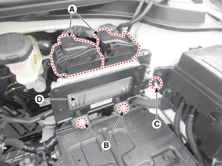
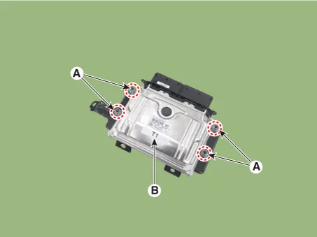
| 5. |
Remove the ECM (B) after loosening the mounting nuts (A) from the bracket.
|
| Installation |
| 1. |
Install in the reverse order of removal. |
| ECM Problem Inspection Procedure |
| 1. |
TEST ECM GROUND CIRCUIT: Measure resistance between ECM and chassis ground using the backside of ECM harness connector as ECM side check point. If the problem is found, repair it.
|
| 2. |
TEST ECM CONNECTOR: Disconnect the ECM connector and visually check the ground terminals on ECM side and harness side for bent pins or poor contact pressure. If the problem is found, repair it. |
| 3. |
If problem is not found in Step 1 and 2, the ECM could be faulty. If so, make sure there were no DTC's before swapping the ECM with a new one, and then check the vehicle again. If DTC's were found, examine this first before swapping ECM. |
| 4. |
RE-TEST THE ORIGINAL ECM: Install the original ECM (may be broken) into a known-good vehicle and check the vehicle. If the problem occurs again, replace the original ECM with a new one. If problem does not occur, this is intermittent problem (Refer to “Intermittent Problem Inspection Procedure” in Basic Inspection Procedure). |
| Adjustment |
| ECM Neutral Mode procedure |
| • |
After replacing the ECM of the vehicle with the immobilizer, the following procedure must be performed. |
|
[If installing a used ECM] |
| 1) |
Perform "ECM Neutral Mode" procedure using KDS/GDS. (Refer to "Body Electrical System - "Immobilizer System - Repair procedures") |
| 2) |
After finishing "ECM Neutral Mode", perform "Key Teaching" procedure using KDS/GDS. (Refer to "Body Electrical System - "Immobilizer System - Repair procedures") |
|
[If installing a new ECM] Perform "Key Teaching" procedure using KDS/GDS. (Refer to "Body Electrical System - "Immobilizer System - Repair procedures") |
| • |
After replacing the ECM of the vehicle with the smart key system (button start), the following procedure must be performed. |
|
[If installing a used ECM] |
| 1) |
Perform "ECM Neutral Mode" procedure using KDS/GDS. (Refer to "Body Electrical System - "Smart key - Repair procedures") |
| 2) |
After finishing "ECM Neutral Mode", turn IGN ON then OFF using the smart key or start button. Then the ECM learns information on the smart key automatically. |
|
[If installing a new ECM] Turn IGN ON then OFF using the smart key or start button. Then the ECM learns information on the smart key automatically. |
ETC module learning procedure
| • |
Perform ETC module learning after replacing the ETC module. (Refer to Engine Control System - "ETC (Electronic Throttle Control) System") |
Components and components location Components Location 1 . ECM (Engine control module) 2 . Manifold Absolute Pressure Sensor (MAPS) 3 .
Specifications Specification ETC Module Throttle Position Sensor (TPS) [integrated into ETC Module] ▷ Type: Hall IC Non-contact sensor type ▷ Specification Throttle angle(°) Output Voltage (V) [Vref=5V] TPS1 TPS2 0 0.
Other information:
Kia Rio 2017-2023 YB Service Manual: Refrigerant line
Repair procedures Replacement 1. Discharge refrigerant from refrigeration system. 2. Replace faulty tube or hose. Cap the open fittings immediately to keep moisture or dirt out of the system.
Kia Rio 2017-2023 YB Service Manual: Auto Defogging Sensor (FATC only)
Description and operation Description The Auto Defogging Sensor is installed on front windshild glass. The Auto Defogging Sensor senses moisture on the windshild. The air conditioner control module receives the signal from the sensor and eliminate the fog by controlling the intake actuator, A/C, auto defogging actuator, blower m
Categories
- Manuals Home
- Kia Rio Owners Manual
- Kia Rio Service Manual
- Maintenance Schedule
- Emission Control System
- Motor Driven Power Steering
- New on site
- Most important about car
