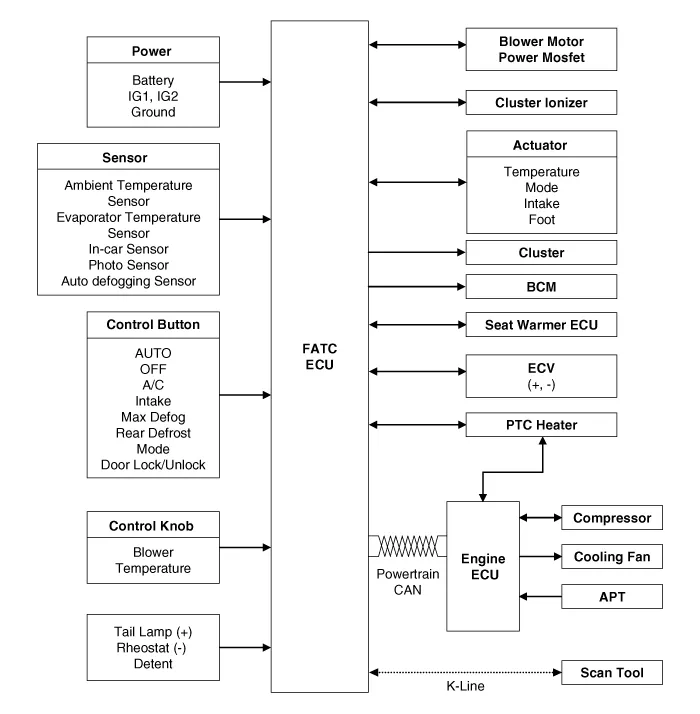
Kia Rio: Controller / Heater & A/C Control Unit (FATC)
Components and components location
| Components |

Connector Pin Function
|
No. |
Connector A |
Connector B |
|
1 |
Battery |
⁻ |
|
2 |
ISG battery (+) |
⁻ |
|
3 |
Illumination (+) |
⁻ |
|
4 |
Sensor (REF) (+) |
Defogging actuator Feedback |
|
5 |
Mode control actuator Feedback |
Defogging actuator (Open) |
|
6 |
Temperature control actuator Feedback |
Defogging actuator (Close) |
|
7 |
Intake actuator Feedback |
⁻ |
|
8 |
Evapoerator sensor (+) |
⁻ |
|
9 |
Ambient sensor (+) |
⁻ |
|
10 |
Mode control actuator (VENT) |
⁻ |
|
11 |
Mode control actuator (DEF) |
Defog current |
|
12 |
Temperature control actuator (COOL) |
Defog temperature |
|
13 |
Temperature control actuator (WARM) |
Defog sck |
|
14 |
Intake actuator (FRE) |
Defog data |
|
15 |
Intake actuator (REC) |
⁻ |
|
16 |
HTD |
Ground |
|
17 |
Rear defog switch |
|
|
18 |
⁻ |
|
|
19 |
⁻ |
|
|
20 |
Illumination (-) |
|
|
21 |
IGN2 |
|
|
22 |
IGN1 |
|
|
23 |
Blower motor (+) |
|
|
24 |
Photo sensor (-) |
|
|
25 |
⁻ |
|
|
26 |
⁻ |
|
|
27 |
⁻ |
|
|
28 |
PTC relay 3 |
|
|
29 |
PTC relay 2 |
|
|
30 |
PTC on signal |
|
|
31 |
Detent out (-) |
|
|
32 |
⁻ |
|
|
33 |
Chassis_CAN (High) |
|
|
34 |
Chassis_CAN (Low) |
|
|
35 |
FET (Drain hose Feedback) |
|
|
36 |
FET (Gate) |
|
|
37 |
ECV (+) |
|
|
38 |
ECV (-) |
|
|
39 |
Sensor ground |
|
|
40 |
Ground |
Schematic diagrams
| Schematic Diagrams |
Repair procedures
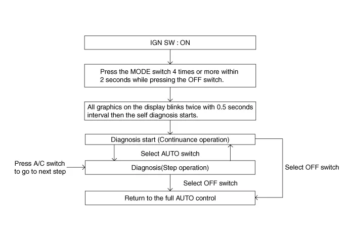
| Self Diagnosis |
| 1. |
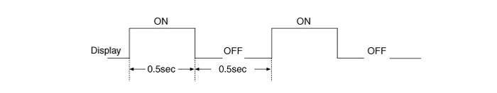
Self-diagnosis process
|
| 2. |
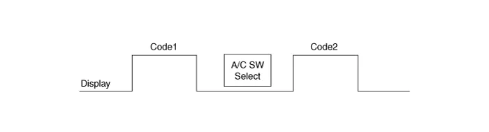
How to read self-diagnostic code During the self-diagnosis, the corresponding fault code flickers on the setup temperature display panel every 0.5 second and will show two figures. Fault codes are displayed in numerical format.
|
| 3. |
Fault code display
|

| 4. |
If fault codes are displayed during the check, inspect malfunction causes by referring to fault codes table. |
| 5. |
Fail safe
|
| Replacement |
| 1. |
Disconnect the negative (-) battery terminal. |
| 2. |
Remove the heater & A/C controller (A) after loosening the mounting unit.
|

| 3. |
Disconnect the connectors (A) and the air hose (B).
|

| 4. |
Installation is the reverse order of removal. |