Kia Rio: Brake System / ABS(Anti-Lock Brake System)
Components and components location
| Components |
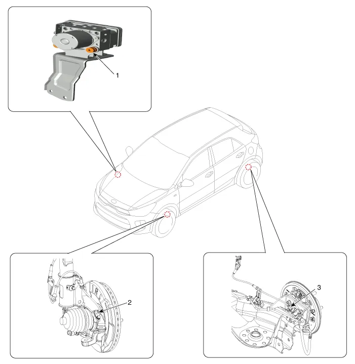
| 1. ABS control module 2. Front wheel speed sensor |
3. Rear wheel speed sensor
|
Description and operation
| Description |
This specification applies to HCU(Hydraulic Control Unit) and ECU(Electronic Control Unit) of the HECU.(Hydraulic and Electronic Control Unit)
This specification is for the wiring design and installation of ABS ECU.
This unit has the functions as follows.
| – |
Input of signal from the wheel speed sensors attached to each wheel. |
| – |
Control of braking force. |
| – |
Failsafe function. |
| – |
Self diagnosis function. |
| – |
Interface with the external diagnosis tester. |
Installation Position : Engine Compartment
| – |
Brake tube length from Master cylinder port to HECU inlet port should be max. 1m |
| – |
The position should not be close to the engine block and not lower than the wheel. |
Operation
The ECU shall be put into operation by switching on the operating voltage (IGN).
On completion of the initialization phase, the ECU shall be ready for operation.
In the operating condition, the ECU shall be ready, within the specified limits (voltage and temperature), to process the signals offered by the various sensors and switches in accordance with the control algorithm defined by the software and to control the hydraulic and electrical actuators.
Wheel Sensor Signal Processing
The ECU shall receive wheel speed signal from the four active wheel sensors.
The wheel signals are converted to voltage signal by the signal conditioning circuit after receiving current signal from active wheel sensors and given as input to the MCU.
Solenoid Valve Control
When one side of the valve coil is connected to the positive voltage that is provided through the valve relay and the other side is connected to the ground by the semiconductor circuit, the solenoid valve goes into operation.
The electrical function of the coils are always monitored by the valve test pulse under normal operation conditions.
Voltage Limits
| – |
Overvoltage When overvoltage is detected(above 16.8 V), the ECU switches off the valve relay and shuts down the system. When voltage is returned to operating range, the system goes back to the normal condition after the initialization phase. |
| – |
Undervoltage In the event of undervoltage(below 9.3 V), ABS control shall be inhibited and the warning lamp shall be turned on. When voltage is returned to operating range, the warning lamp is switched off and ECU returns to normal operating mode. |
Pump Motor Checking
The ECU performs a pump motor test at a speed of 30km/h once after IGN is switched on.
Diagnostic Interface
Failures detected by the ECU are encoded on the ECU, stored in a EEPROM and read out by diagnostic equipment when the ignition switch is turned on.
The diagnosis interface can also be used for testing the ECU during production of the ECU and for actuating the HCU (Air-bleeding line or Roll and Brake Test line).
Warning Lamp Module
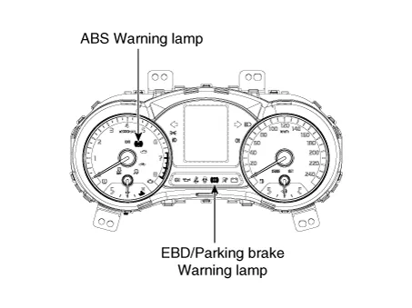
| 1. |
ABS Warning Lamp The active ABS warning lamp indicates the selftest and failure status of the ABS. The ABS warning lamp shall be on:
|
| 2. |
EBD/Parking brake Warning Lamp The active EBD warning lamp indicates the selftest and failure status of the EBD. However, in case the Parking Brake Switch is turned on, the EBD warning lamp is always turned on regardless of EBD functions.The EBD warning lamp shall be on:
|
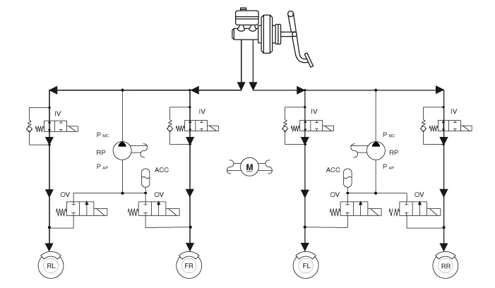
| ABS Control |
| 1. |
Normal Braking without ABS
|
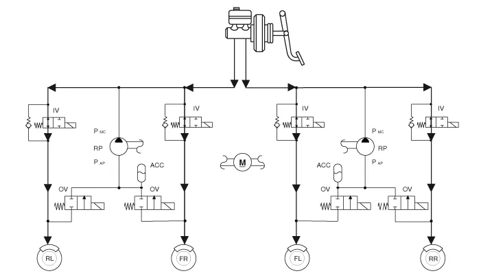

| 2. |
Decrease Mode
|
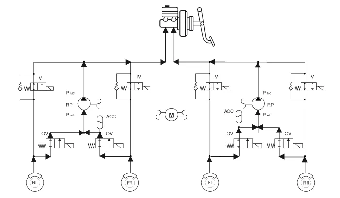
| 3. |
Hold Mode
|
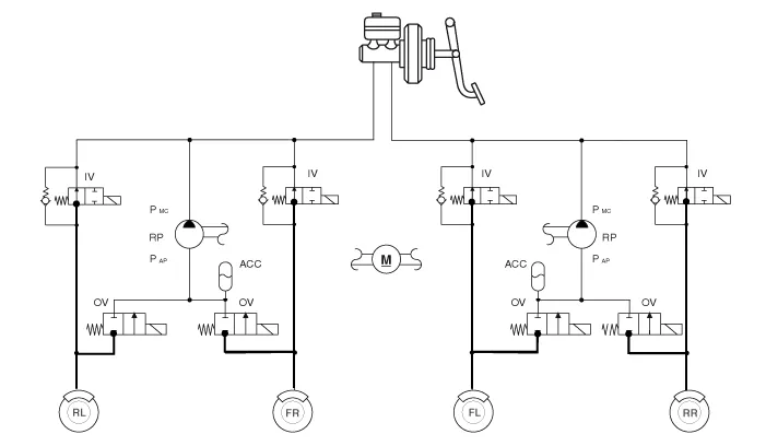
| 4. |
Increase Mode
|
Schematic diagrams
| Circuit Diagram |
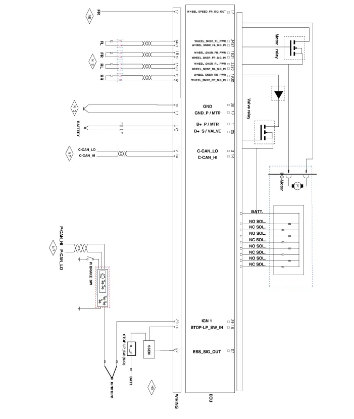
| Terminal Function |
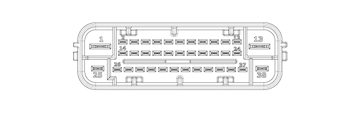
|
Pin No |
Description |
Current |
Resistance |
Remark |
|
(AMPS) |
(mΩ) |
|||
|
1 |
B+ PUMP MOTOR POWER |
137(RUSH) |
10 |
|
|
2 |
C-CAN Low |
30 mA |
250 |
|
|
13 |
GND_PUMP MOTOR GROUND |
137(RUSH) |
10 |
|
|
14 |
C-CAN High |
30 mA |
250 |
|
|
16 |
BRAKE LIGHT SWITCH |
10 mA |
250 |
|
|
17 |
WHEEL SPEED OUTPUT (FR) |
16mA |
250 |
|
|
18 |
WHEEL SPEED SENSOR POWER (FR) |
30 mA |
250 |
|
|
19 |
WHEEL SPEED SENSOR POWER (RR) |
30 mA |
250 |
|
|
20 |
WHEEL SPEED SENSOR SIGNAL GROUND (RL) |
16.8 mA |
250 |
|
|
21 |
WHEEL SPEED SENSOR SIGNAL GROUND (FL) |
16.8 mA |
250 |
|
|
25 |
BATTERTY(+) SOLENOID |
40 |
10 |
|
|
27 |
ESS DRIVE SIGNAL |
200mA |
250 |
|
|
29 |
IGNITION1 |
50mA |
60 |
|
|
31 |
WHEEL SPEED SENSOR SIGNAL GROUND (FR) |
16.8mA |
250 |
|
|
32 |
WHEEL SPEED SENSOR SIGNAL GROUND (RR) |
16.8mA |
250 |
|
|
33 |
WHEEL SPEED SENSOR POWER (RL) |
30mA |
250 |
|
|
34 |
WHEEL SPEED SENSOR POWER (FL) |
30mA |
250 |
|
|
38 |
GROUND |
40 |
10 |
|
Components and components location Components 1. Parking brake lever 2. Equalizer assembly 3. Rear parking brake cable Repair procedures Removal Rear Disc Brake Type The parking brake cables must not be bent or distorted.
Components and components location Components 1. ABS control module connector 2. ABS control module 3. ABS bracket Repair procedures Removal 1.
Other information:
Kia Rio 2017-2023 YB Service Manual: Horn
Components and components location Component Location 1. Horn switch 2. Horn relay 3. Horn 4. Clock spring Repair procedures Removal 1. Remove the front bumper assembly.
Kia Rio 2017-2023 YB Service Manual: Power Door Lock Switch
Repair procedures Removal • When removing with a flat-tip screwdriver or remover, wrap protective tape around the tools to prevent damage to components.
Categories
- Manuals Home
- Kia Rio Owners Manual
- Kia Rio Service Manual
- Motor Driven Power Steering
- Maintenance
- Steering System
- New on site
- Most important about car
