Kia Rio: ABS(Anti-Lock Brake System) / Rear Wheel Speed Sensor
Components and components location
| Components |
Drum type

Disc type

Repair procedures
| Removal |
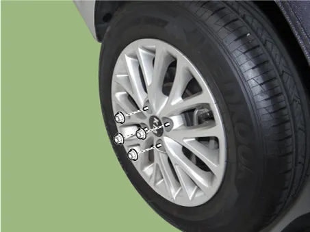
| 1. |
Remove the rear wheel & tire.
|
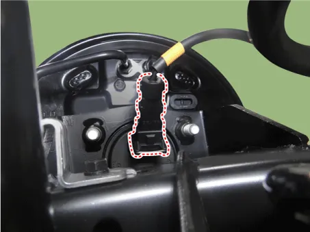
| 2. |
Disconnect the rear wheel speed sensor.
|
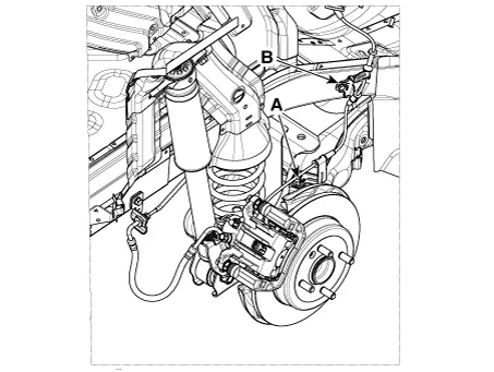
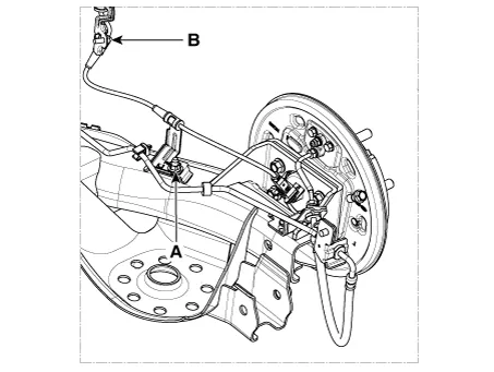
| 3. |
Loosen the nut (A) and bolt (B).
Drum type
Disc type
|
| 4. |
Remove the rear seat. (Refer to body -"Rear Seat Assembly") |
| 5. |
Remove the door scuff trim. (Refer to body -"Door Scuff Trim") |
| 6. |
Disconnect the rear wheel speed sensor connector. |
| Inspection |
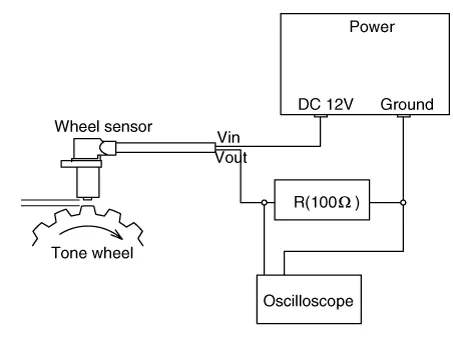
| 1. |
Measure the output voltage between the terminal of the wheel speed sensor and the body ground.
|

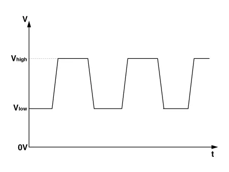
| 2. |
Compare the change of the output voltage of the wheel speed sensor to the normal change of the output voltage as shown below.
|
| Replacement |
Rear Wheel Speed Sensor Cap
| 1. |
Remove the rear wheel hub bearing assembly. (Refer to Driveshaft and axle - "Rear Axle Assembly") |
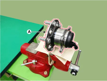
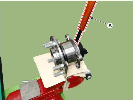
| 2. |
Fix the rear hub bearing assembly (A) on the vise.
|
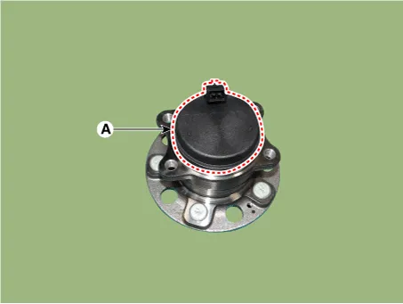
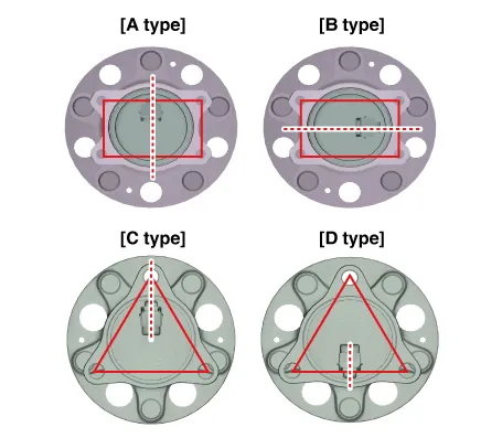
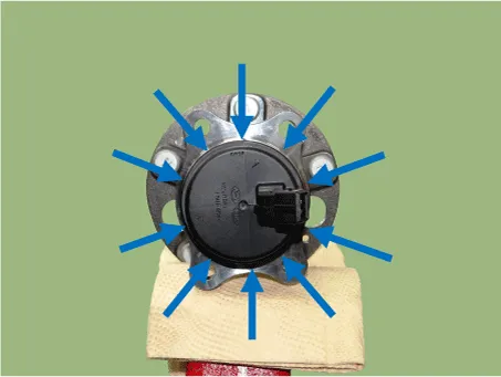
| 3. |
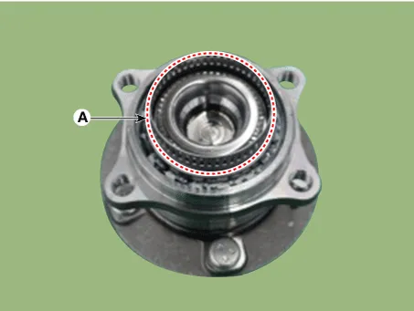
Check the direction of the sensor cap (A).
|
| 4. |
Remove the sensor cap by hammering on a gap between sensor cap and hub bearing assembly using a scraper (A).
|
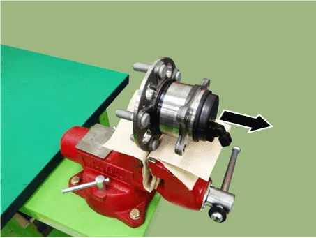
| 5. |
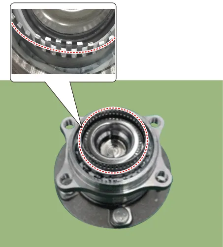
Check if distorted or damaged the tone wheel or encoder (A).
|
| 6. |
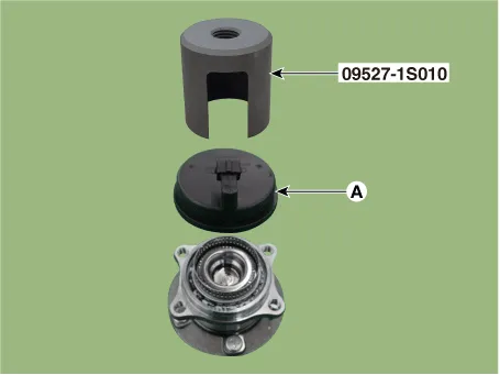
Position the sensor cap to the same direction of sensor cap connector (A) as you checked before removing.
|
| 7. |
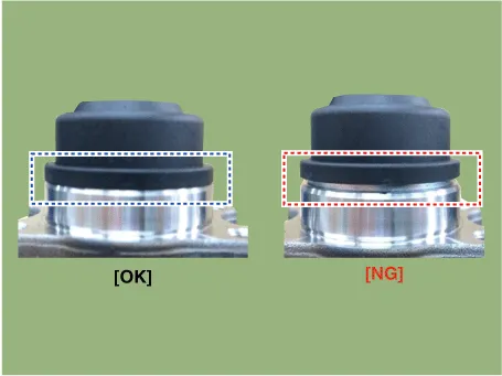
Install the sensor cap (A) with the special service tool (09527-1S010).
|
| 8. |
Install the rear wheel hub bearing assembly. (Refer to Driveshaft and axle - "Rear Axle Assembly") |
Components and components location Components 1. Front wheel speed sensor connector 2. Front wheel speed sensor Repair procedures Removal 1.
Components and components location Components 1. ESC control module 2. Front wheel speed sensor 3. Rear wheel speed sensor Description and operation Description of ESC Electronic Stability Control (ESC) recognizes critical driving conditions, such as panic reactions in dangerous situations, and stabilizes the vehicle by wheel-individual braking and engine control intervention.
Other information:
Kia Rio 2017-2023 YB Service Manual: Lane Departure Warning System (LDWS)
Components and components location Components 1. LDWS ON/OFF switch 2. Instrument cluster 3. LDWS unit (MFC) ※ MFC : Multi Function Camera – Function : LDWS, HBA, AEB Description and operation Description System block diagram Components of LDWS
Kia Rio 2017-2023 YB Service Manual: Room Lamp
Repair procedures Removal • Put on gloves to prevent hand injuries. • When removing with a flat-tip screwdriver or remover, wrap protective tape around the tools to prevent damage to componen
Categories
- Manuals Home
- Kia Rio Owners Manual
- Kia Rio Service Manual
- Steering System
- Suspension System
- Brake System
- New on site
- Most important about car
