Kia Rio: ABS(Anti-Lock Brake System) / Front Wheel Speed Sensor
Components and components location
| Components |
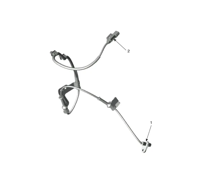
| 1. Front wheel speed sensor connector
|
2. Front wheel speed sensor
|
Repair procedures
| Removal |
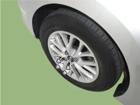
| 1. |
Remove the front wheel & tire.
|
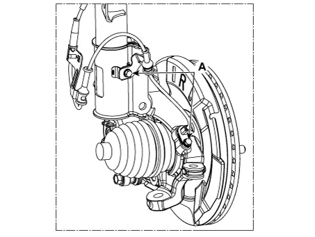
| 2. |
Loosen the bolt (A) and then disconnect the wheel speed sensor.
|
| 3. |
Remove the front wheel guard. (Refer to Body - "Front Wheel Guard") |
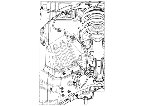
| 4. |
Disconnect the wheel speed sensor connector (A).
|
| 5. |
Install in the reverse order of removal. |
| Inspection |
| 1. |
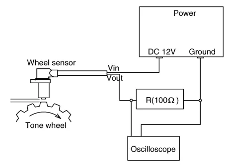
Measure the output voltage between the terminal of the wheel speed sensor and the body ground.
|

| 2. |
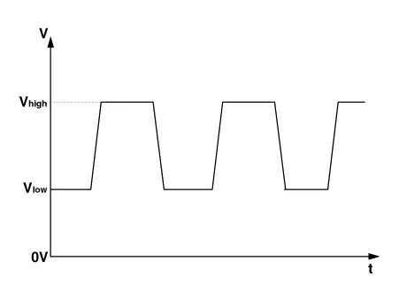
Compare the change of the output voltage of the wheel speed sensor to the normal change of the output voltage as shown below.
|
Components and components location Components 1. ABS control module connector 2. ABS control module 3. ABS bracket Repair procedures Removal 1.
Components and components location Components Drum type Disc type Repair procedures Removal 1. Remove the rear wheel & tire.
Other information:
Kia Rio 2017-2023 YB Service Manual: Horn
Components and components location Component Location 1. Horn switch 2. Horn relay 3. Horn 4. Clock spring Repair procedures Removal 1. Remove the front bumper assembly.
Kia Rio 2017-2023 YB Service Manual: Front Wiper Motor
Components and components location Component Location 1. Cap 2. Nut 3. Wiper arm & blade 4. Cowl top cover 5. Bolt 6. Wiper motor & linkage assembly 7. Wiper motor connector Repair procedures Removal 1.
Categories
- Manuals Home
- Kia Rio Owners Manual
- Kia Rio Service Manual
- Brake System
- Body (Interior and Exterior)
- General Information
- New on site
- Most important about car
