Kia Rio: ABS(Anti-Lock Brake System) / ABS Control Unit
Components and components location
| Components |
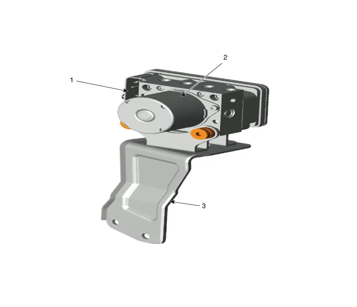
| 1. ABS control module connector
2. ABS control module |
3. ABS bracket |
Repair procedures
| Removal |
| 1. |
Turn ignition OFF and disconnect the negative (-) battery cable. |
| 2. |
Remove the brake fluid from the master cylinder reservoir with a syringe.
|

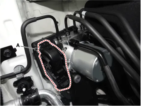
| 3. |
Pull up the lock of the ABS connector (A) and then disconnect the connector.
|
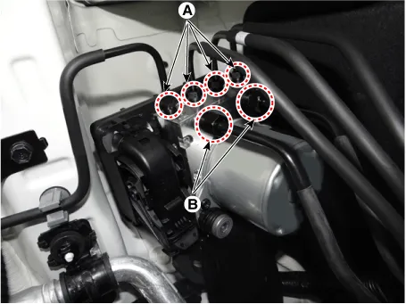
| 4. |
Disconnect the brake tubes from the ABS by unlocking the nuts counterclockwise with a wrench.
|
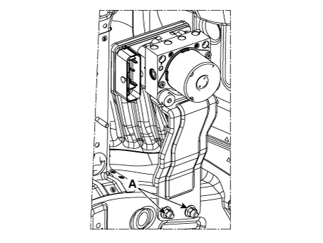
| 5. |
Loosen the ABS control module bracket nuts (A), and then remove the ABS control module bracket.
|
| Installation |
| 1. |
Install in the reverse order of removal. |
| 2. |
After installation, bleed the brake system. (Refer to Brake system - "Brake System") |
| 3. |
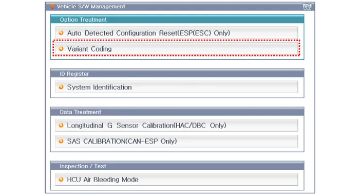
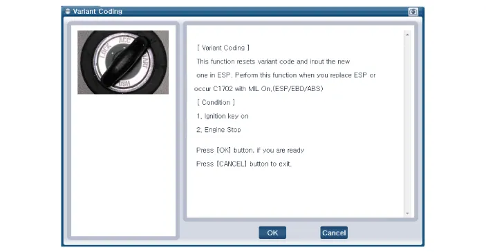
Conduct the Variant coding. |
| 4. |
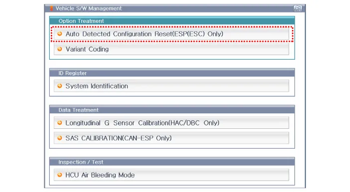
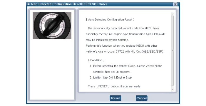
Conduct the Auto Detected Sensor Calibration. |
| 5. |
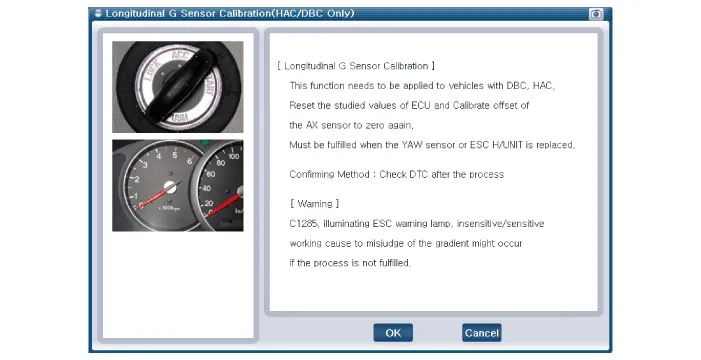
Conduct the Longitudinal G Sensor Calibration. |
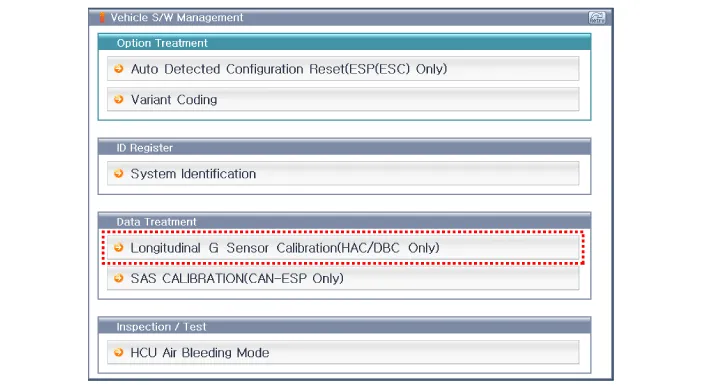
| Diagnostic procedure by using diagnostic device |
Perform diagnostic procedure by using diagnostic device as shown below:
Connect self-diagnosis connector (16pins) located under the driver side crash pad to self-diagnosis device, and then turn the self-diagnosis device after key is ON.
Select the "vehicle model" and "ABS/ESC" on GDS vehicle selection screen, then select OK.
| [Variant Coding] |
| [Auto Detected Sensor Calibration] |
| [Longitudinal G Sensor Calibration] |
Components and components location Components 1. ABS control module 2. Front wheel speed sensor 3. Rear wheel speed sensor Description and operation Description This specification applies to HCU(Hydraulic Control Unit) and ECU(Electronic Control Unit) of the HECU.
Components and components location Components 1. Front wheel speed sensor connector 2. Front wheel speed sensor Repair procedures Removal 1.
Other information:
Kia Rio 2017-2023 YB Service Manual: Auto Defogging Sensor (FATC only)
Description and operation Description The Auto Defogging Sensor is installed on front windshild glass. The Auto Defogging Sensor senses moisture on the windshild. The air conditioner control module receives the signal from the sensor and eliminate the fog by controlling the intake actuator, A/C, auto defogging actuator, blower m
Kia Rio 2017-2023 YB Service Manual: Power Mosfet (FATC)
Repair procedures Inspection 1. Turn the ignition switch ON. 2. Manually operate the control switch and measure the voltage of blower motor. 3. Select the control switch to raise voltage until high speed.
Categories
- Manuals Home
- Kia Rio Owners Manual
- Kia Rio Service Manual
- Cooling System
- Engine Mechanical System
- Brake System
- New on site
- Most important about car
