
Kia Rio: Cooling System / Radiator
Components and components location
| Components |
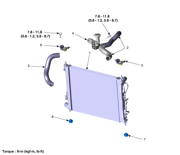
| 1. Radiator 2. Radiator upper hose 3. Radiator lower hose 4. Filler neck assembly |
5. Radiator upper mounting bracket
[LH] 6. Radiator upper mounting bracket [RH] 7. Radiator lower mounting insulator [LH] 8. Radiator lower mounting insulator [RH] |
Repair procedures
| Removal and Installation |
| 1. |
Disconnect the battery negative terminal. |
| 2. |
Remove the engine room under cover. (Refer to Engine and Transaxle Assembly - "Engine Room Under Cover") |
| 3. |
Drain the coolant. (Refer to Cooling System - "Coolant") |
| 4. |
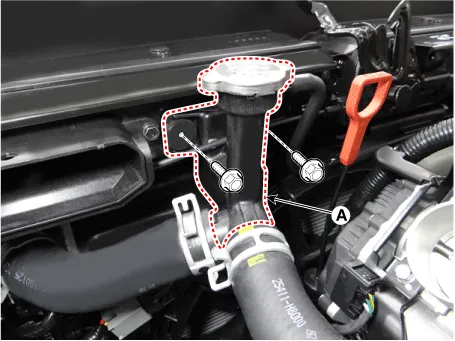
Separate the filler neck assembly (A).
|
| 5. |
Disconnect the radiator upper hose (A).
|

| 6. |
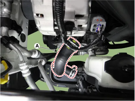
Disconnect the radiator lower hose (A).
|
| 7. |
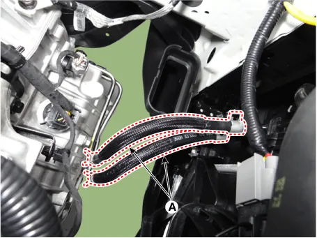
Disconnect the ATF cooler hoses (A). (A/T only)
|
| 8. |
Remove the cooling fan assembly. (Refer to Cooling System - "Cooling Fan") |
| 9. |
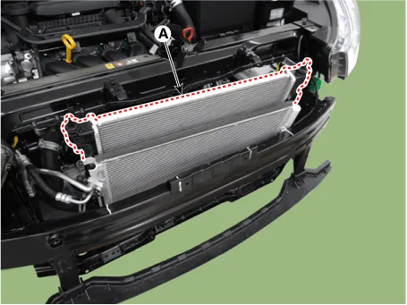
Separate the condenser and then remove the radiator (A).
|
| 10. |
Install in the reverse order of removal. |
| 11. |
Fill with engine coolant. (Refer to Cooling System - "Coolant") |
| 12. |
Start engine and check for leaks. |
| 13. |
Recheck engine coolant level. |
| Inspection |
Radiator Cap Testing
| 1. |
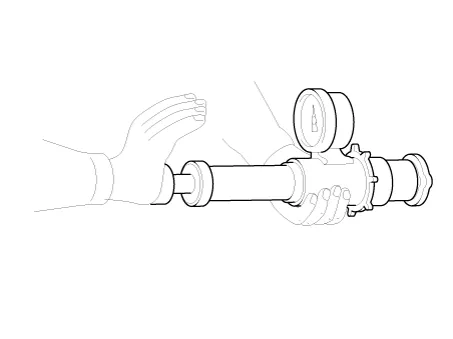
Remove the radiator cap, wet its seal with engine coolant, and then install it on a pressure tester.
|
| 2. |
Apply a pressure of 93.2 - 122.6 kPa (0.95-1.25 kgf/cm², 13.51-17.78 psi). |
| 3. |
Check for a drop in pressure. |
| 4. |
If the pressure drops, replace the cap. |
Radiator Leakage Test
| 1. |
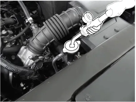
Wait until engine is cool, then carefully remove the radiator cap and fill the radiator with engine coolant, then install it on the pressure tester. |
| 2. |
Apply a pressure tester to the radiator and apply a pressure of 93.16 - 122.58 kPa (0.95 - 1.25 kgf/cm², 13.51 - 17.78 psi).
|
| 3. |
Inspect for engine coolant leaks and a drop in pressure. |
| 4. |
Remove the tester and reinstall the radiator cap.
|

Components and components location Components 1. Cooling fan 3. Cooling fan shroud 2. Fan motor 4. Radiator Specifications Specifications Item Specification 120W 160W 180W Fan type Puller Puller Puller Fan speed control Resistor Resistor Resistor Air flow rate [㎥/h] 1,700 - 8% min.
Repair procedures Removal and Installation 1. Remove the engine room under cover. (Refer to Engine and Transaxle Assembly - "Engine Room Under cover") 2.
Other information:
Kia Rio 2017-2023 YB Service Manual: Immobilizer Control Unit
Repair procedures Removal 1. Disconnect the negative (-) battery terminal. 2. Remove the main crash pad assembly. (Refer to Body - "Main Crash Pad Assembly") 3. Disconnect the connector of the immobilizer unit and then remove the immobilizer unit (A) after
Kia Rio 2017-2023 YB Service Manual: Photo Sensor (FATC only)
Description and operation Description The photo sensor is located at the center of defrost nozzles. The photo sensor contains a photovoltaic (sensitive to sunlight) diode. The solar radiation received by its light receiving portion, generates an electromotive force in proportion to the amount of radiation received which is tran
Categories
- Manuals Home
- Kia Rio Owners Manual
- Kia Rio Service Manual
- Timing Chain
- Filler-Neck Assembly
- Fuse/relay panel description
- New on site
- Most important about car
