Kia Rio: Cooling System / Water Temperature Control Assembly
Repair procedures
| Removal and Installation |
| 1. |
Remove the engine room under cover. (Refer to Engine and Transaxle Assembly - "Engine Room Under cover") |
| 2. |
Drain the coolant. (Refer to Cooling System - "Coolant") |
| 3. |
Remove the air cleaner assembly. (Refer to Intake and Exhaust System - "Air Cleaner") |
| 4. |
Remove the battery. (Refer to Engine Electrical System - "Battery") |
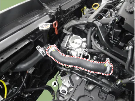
| 5. |
Disconnect the radiator upper hose (A).
|
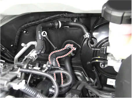
| 6. |
Disconnect the heater hose (A).
|
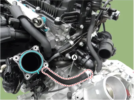
| 7. |
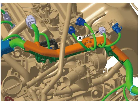
Disconnect the coolant hose (A).
|
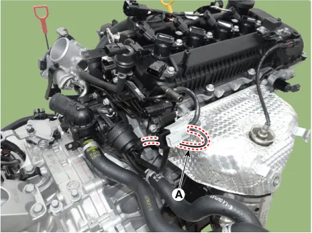
| 8. |
Disconnect the vacuum hose (A).
|
| 9. |
Disconnect the engine coolant temperature sensor (ECTS) connector (A).
|
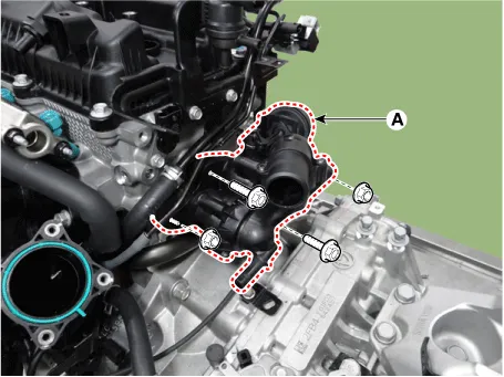
| 10. |
Remove the water temperature control assembly (A).
|
| 11. |
Install in the reverse order of removal. |
| 12. |
Fill the coolant. (Refer to Cooling System - "Coolant") |
| 13. |
Start the engine and check for leasks. |
| 14. |
Recheck the engine coolant level. |
Components and components location Components 1. Radiator 2. Radiator upper hose 3. Radiator lower hose 4. Filler neck assembly 5.
Repair procedures Removal and Installation 1. Disconnect the battery negative terminal. 2. Drain the coolant.
Other information:
Kia Rio 2017-2023 YB Service Manual: Heater Unit
Components and components location Component Location Components 1. Heater pipe cover 2. Heater core 3. Mode control actuator 4. Mode control actuator bracket 5. Mode control main lever 6.
Kia Rio 2017-2023 YB Service Manual: PTC Heater
Description and operation Description The PTC (Positive Temperature Coefficient) heater is installed at the exit or the backside of heater core. The PTC heater is an electric heater using a PTC element as an auxiliary heating device that supplements deficiency of interior heat source in highly effective diesel engine.
Categories
- Manuals Home
- Kia Rio Owners Manual
- Kia Rio Service Manual
- Timing Chain
- Cooling System
- Engine Control / Fuel System
- New on site
- Most important about car
