Kia Rio: Intake And Exhaust System / Intake Manifold
Components and components location
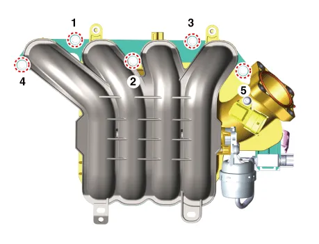
| Components |

| 1. Intake manifold 2. Intake manifold gasket 3. Positive crankcase ventilation (PCV) hose |
4. Purge control solenoid valve
(PCSV) hose 5. Manifold absolute pressure sensor (MAPS) |
Repair procedures
| Removal and Installation |
| 1. |
Disconnect the battery negative terminal. |
| 2. |
Remove the air cleaner assembly. (Refer to Intake and Exhaust System - "Air Cleaner") |
| 3. |
Disconnect the wiring connectors and harness clamps and remove the connector brackets around the intake manifold.
|

| 4. |
Unfasten the electronic throttle body control (ETC) module bolts. (Refer to Engine Control/Fuel System - "ETC (Electronic throttle body control) System") |
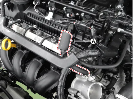
| 5. |
Disconnect the positive crankcase ventilation (PCV) hose (A).
|
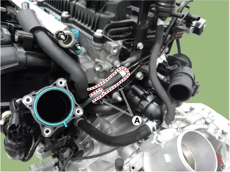
| 6. |
Disconnect the vacuum hose (A).
|
| 7. |
Remove the oilv level gauge. (Refer to Lubrication System -"Oil Level Gauge & Pipe") |
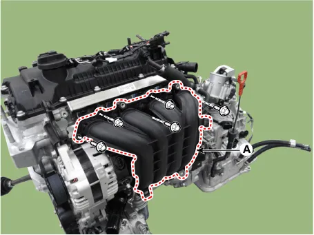
| 8. |
Remove the intake manifold (A).
|

| 9. |
Installation is reverse order of removal. |
Components and components location Comoinents 1. Air intake shield 2. Heat shield 3. Air duct 4. Duct extension 5.
Components and components location Components 1. Exhaust manifold gasket 2. Exhaust manifold 3. Exhaust manifold stay 4.
Other information:
Kia Rio 2017-2023 YB Service Manual: Indicators And Gauges
Troubleshooting Troubleshooting Error Item Failure symptom Inspection items Detailed inspections Relevant Parts/ Components Screen display LCD screen does not turn on 1) Connector attachments
Kia Rio 2017-2023 YB Service Manual: Refrigerant line
Repair procedures Replacement 1. Discharge refrigerant from refrigeration system. 2. Replace faulty tube or hose. Cap the open fittings immediately to keep moisture or dirt out of the system.
Categories
- Manuals Home
- Kia Rio Owners Manual
- Kia Rio Service Manual
- Cooling System
- Coolant
- Engine Mechanical System
- New on site
- Most important about car
