Kia Rio: Intake And Exhaust System / Air Cleaner
Components and components location
| Comoinents |
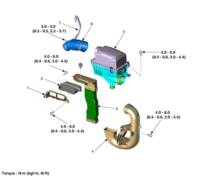
| 1. Air intake shield 2. Heat shield 3. Air duct 4. Duct extension |
5. Air cleaner assembly 6. Air intake hose 7. Breather hose |
Repair procedures
| Removal and Installation |
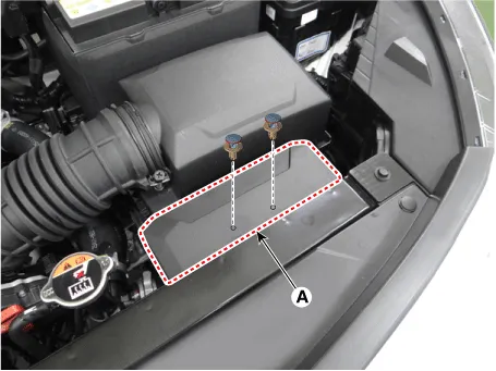
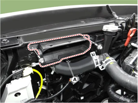
Air Duct
| 1. |
Remove the air duct (A).
|
| 2. |
Install in the reverse order of removal. |
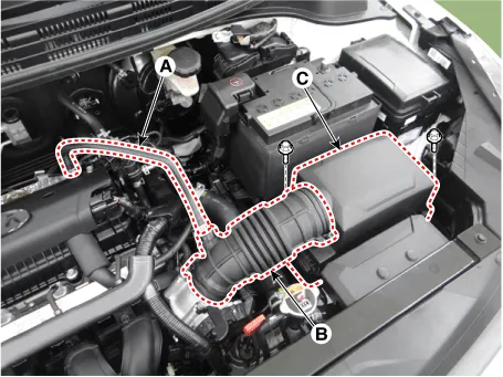
Air Cleaner Assembly
| 1. |
Disconnect the breather hose (A). |
| 2. |
Disconnect the air intake hose (B). |
| 3. |
Remove the air cleaner assembly (C).
|
| 4. |
Install in the reverse order of removal. |
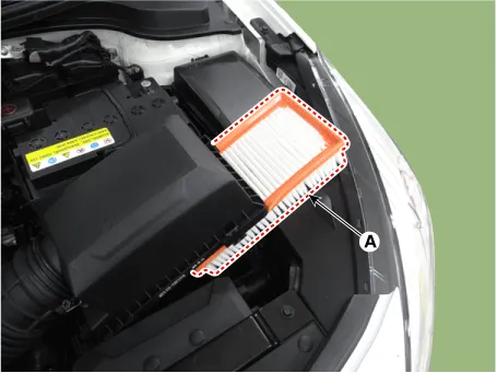
Air Cleaner Element
| 1. |
Open the air cleaner element cover (A) by unlocking the clamp.
|
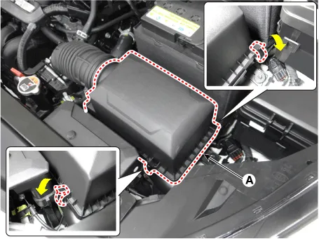
| 2. |
Replace the air cleaner element (A) with a new one.
|

| 3. |
Close the air cleaner cover by hooking the clamps. |
Extension Duct
| 1. |
Remove the air duct and air cleaner assembly. |
| 2. |
Remove the engine room under cover. (Refer to Engine And Transaxle Assembly - "Engine Room Under Cover") |
| 3. |
Remove the extension duct (A).
|
| 4. |
Install in the reverse order of removal. |
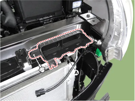
Heat Shield
| 1. |
Remove the air duct. |
| 2. |
Remove the heat shield (A).
|
| 3. |
Install in the reverse order of removal. |
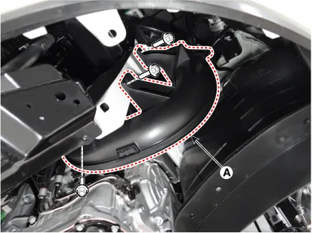
Air Intake Shield
| 1. |
Remover the front bumper assembly. (Refer to body (Interior and Exterior) - "Front Bumper Assembly") |
| 2. |
Remove the air intake shield (A).
|
| 3. |
Install in the reverse order of removal. |
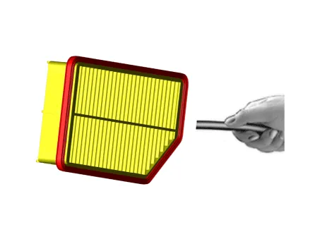
| Inspection |
| 1. |
Remove the air cleaner element. |
| 2. |
Check if the air filter is excessively dirty. If so, replace the air cleaner element. |
| 3. |
If the air cleaner element needs to be cleaned, blow compressed air as shown in the illustration to clean it.
|
| 4. |
Reinstall the air cleaner element. |
Components and components location Components 1. Intake manifold 2. Intake manifold gasket 3. Positive crankcase ventilation (PCV) hose 4.
Other information:
Kia Rio 2017-2023 YB Service Manual: Rheostat
Components and components location Components Repair procedures Removal 1. Disconnect the negative (-) battery terminal. 2. Remove the crash pad lower panel. (Refer to Body - "Crash Pad Lower Panel") 3.
Kia Rio 2017-2023 YB Service Manual: High Mounted Stop Lamp
Repair procedures Removal 1. Disconnect the negative (-) battery terminal. 2. Open the tailgate. 3. Remove the high mounted stop lamp (A) after loosening the mounting nuts.
Categories
- Manuals Home
- Kia Rio Owners Manual
- Kia Rio Service Manual
- Clutch System
- Engine Mechanical System
- General Information
- New on site
- Most important about car
