Kia Rio: Intake And Exhaust System / Exhaust Manifold
Components and components location
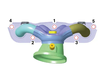
| Components |

| 1. Exhaust manifold gasket
2. Exhaust manifold |
3. Exhaust manifold stay 4. Heat protector |
Repair procedures
| Removal and Installation |
| 1. |
Disconnect the negative battery terminal. |
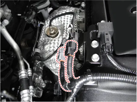
| 2. |
Disconnect the oxygen sensor connector (A).
|
| 3. |
Remove the front muffler. (Refer to Intake And Exhaust System - "Muffler") |
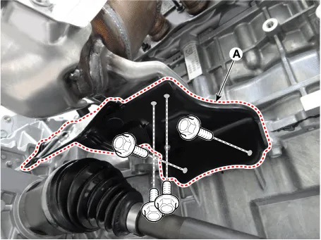
| 4. |
Remove the exhaust manifold stay (A).
|
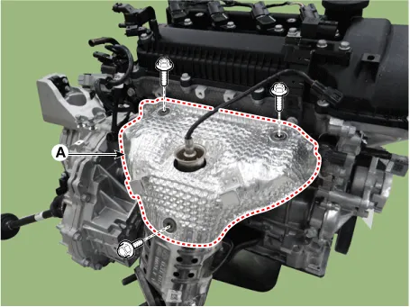
| 5. |
Remove the heat protector (A).
|
| 6. |
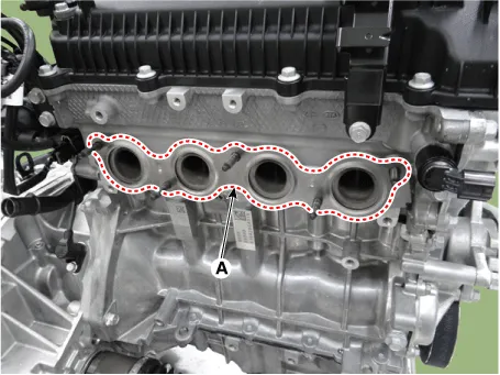
Remove the exhaust manifold (A).
|
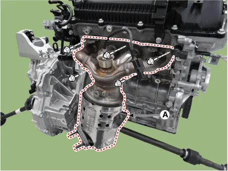
| 7. |
Remove the exhaust manifold gasket (A).
|
| 8. |
Install in the reverse order of removal.
|

Components and components location Components 1. Intake manifold 2. Intake manifold gasket 3. Positive crankcase ventilation (PCV) hose 4.
Repair procedures Removal and Installation Front Muffler 1. Disconnect the rear oxygen sensor (A). 2.
Other information:
Kia Rio 2017-2023 YB Service Manual: Lane Departure Warning System (LDWS) Unit
Components and components location Components Repair procedures Removal When replacing the LDWS switch, check that the symbol mark in the cluster operates normally by pressing the ON/OFF switch.
Kia Rio 2017-2023 YB Service Manual: Multifunction Switch
Specifications Specifications Items Specifications Rated voltage DC 12 V Operating temperature range -22 - 176°F (-30 - 80°C) Rated load Washer Washer : 6A (Motor load) Components and components
Categories
- Manuals Home
- Kia Rio Owners Manual
- Kia Rio Service Manual
- Heating,Ventilation, Air Conditioning
- Clutch System
- Timing Chain
- New on site
- Most important about car
