Kia Rio: Engine Control System / Heated Oxygen Sensor (HO2S)
Specifications
| Specification |
Heated Oxygen Sensor (HO2S)
HO2S [Bank 1/Sensor 1]
|
Item |
Specification |
|
Heater Resistance (Ω) |
Approximately 9.0 [20°C(68°F)] |
|
Type |
Binary |
|
Pin |
4 |
HO2S [Bank 1/Sensor 2]
|
Item |
Specification |
|
Heater Resistance (Ω) |
Approximately 9.0 [20°C(68°F)] |
|
Type |
Binary |
|
Pin |
4 |
Description and operation
| Description |
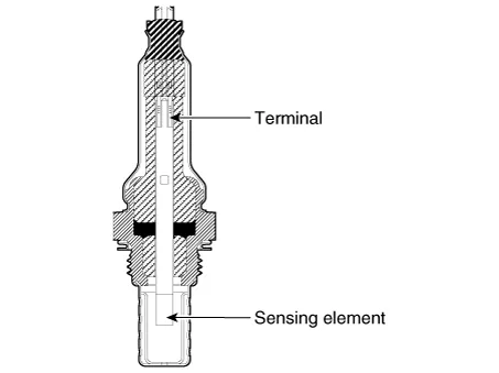
Heated Oxygen Sensor (HO2S) consists of zirconium and alumina and is installed on upstream and downstream of the Warm up Catalytic Converter (WCC).
After it compares oxygen consistency of the atmosphere with the exhaust gas, it transfers the corresponding voltage signal to the ECM. When A/F ratio is rich or lean, it generates approximately +1V or 0V respectively.
In order that this sensor normally operates, the temperature of the sensor tip must be higher than predetermined temperature. So it has a heater which is controlled by the ECM duty signal. When the exhaust gas temperature is lower than the specified value, the heater warms the sensor tip.
Schematic diagrams
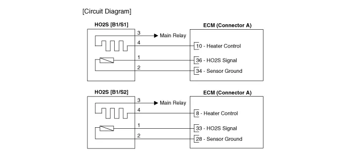
| Circuit Diagram |
Repair procedures
| Inspection |
| 1. |
Check signal waveform of HO2S using a KDS/GDS.
|
| 2. |
Turn the ignition switch OFF. |
| 3. |
Disconnect the HO2S connector. |
| 4. |
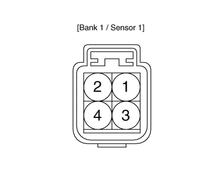
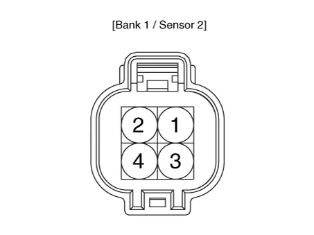
Measure resistance between HO2S heater terminals 3 and 4. |
| 5. |
Check that the resistance is within the specification.
|
| Removal |
Note that the SST (Part No.: 09392-2H100 or 09392-1Y100) is useful when removing the heated oxygen sensor. |

| 1. |
Turn the ignition switch OFF and disconnect the battery negative (-) terminal. |
| 2. |
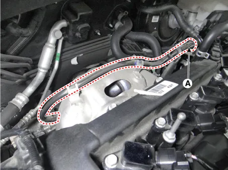
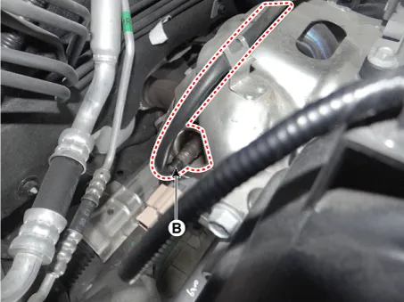
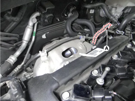
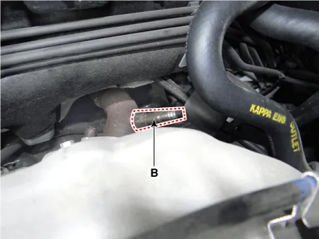
Disconnect the connector (A), and then remove the sensor (B).
[Bank 1 / Sensor 1]
[Bank 1 / Sensor 2]
|
| Installation |
|
| 1. |
Installation is reverse of removal. |
Troubleshooting
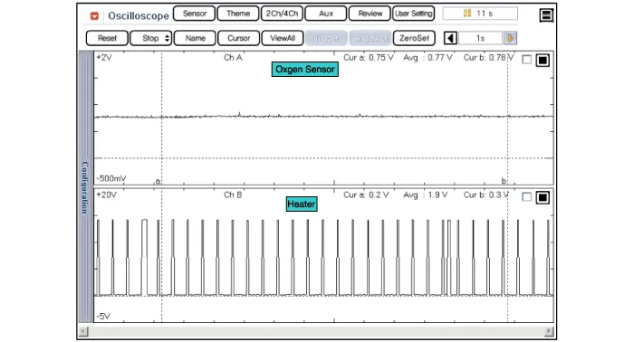
| Waveform |
| [Sensor 1, 2] |
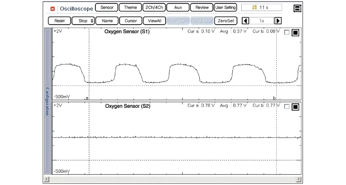
| [Bank 1 / Sensor 1] |
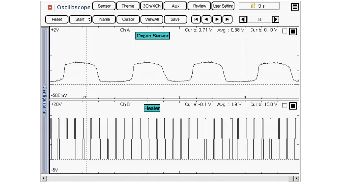
| [Bank 1 / Sensor 2] |
Specifications Specification Knock Sensor (KS) Item Specification Resistance(MΩ) 4.
Specifications Specification Accelerator Position Output Voltage (V) [Vref = 5V] APS1 APS2 C.
Other information:
Kia Rio 2017-2023 YB Service Manual: Power Door Mirrors
C
Kia Rio 2017-2023 YB Service Manual: Blower Resistor (MANUAL)
Repair procedures Inspection 1. Measure the resistance between the terminals. 2. The measured resistance is not within specification, the blower resistor must be replaced. (After removing the resistor) Replacement 1.
Categories
- Manuals Home
- Kia Rio Owners Manual
- Kia Rio Service Manual
- Clutch System
- Suspension System
- Coolant
- New on site
- Most important about car
