Kia Rio: Engine Control System / Accelerator Position Sensor (APS)
Specifications
| Specification |
|
Accelerator Position |
Output Voltage (V) [Vref = 5V] |
|
|
APS1 |
APS2 |
|
|
C.T |
0.7 - 0.8 |
0.32 - 0.42 |
|
W.O.T |
3.98 - 4.22 |
1.93 - 2.17 |
Description and operation
| Description |
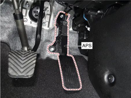
Accelerator Position Sensor (APS) is installed on the accelerator pedal module and detects the rotation angle of the accelerator pedal. The APS is one of the most important sensors in engine control system, so it consists of the two sensors which adapt individual sensor power and ground line. The second sensor monitors the first sensor and its output voltage is half of the first one. If the ratio of the sensor 1 and 2 is out of the range (approximately 1/2), the diagnostic system judges that it is abnormal.
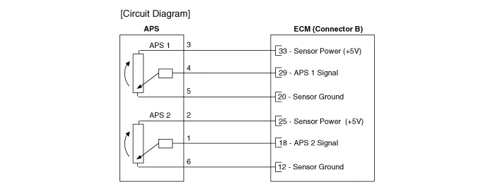
Schematic diagrams
| Circuit Diagram |
Repair procedures
| Inspection |
| 1. |
Connect the KDS/GDS on the Diagnosis Link Connector (DLC). |
| 2. |
Start engine and check output voltages of APS 1 and 2 at C.T and W.O.T.
|
|||||||||||
| Removal |
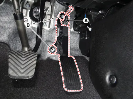
| 1. |
Turn the ignition switch OFF and disconnect the battery negative (-) terminal. |
| 2. |
Disconnect the accelerator position sensor connector (A). |
| 3. |
Remove the installation nuts (B) and then remove the accelerator pedal module.
|
| Installation |
| 1. |
Install in the reverse order of removal. |
Specifications Specification Heated Oxygen Sensor (HO2S) HO2S [Bank 1/Sensor 1] Item Specification Heater Resistance (Ω) Approximately 9.
Specifications Specification Injector Item Specification Coil Resistance (Ω) Approximately 9.
Other information:
Kia Rio 2017-2023 YB Service Manual: Smart Key System
Specifications Specifications Smart Key Unit Items Specification Rated voltage DC 12 V Operating voltage DC 9 - 16 V Operating temperature -31 - 167°F (-35 - 75°C) Load Max.
Kia Rio 2017-2023 YB Service Manual: Cluster Ionizer (FATC only)
Description and operation Description The cluster ionizer helps to clean up odors in the vehicle or from the air-conditioner system. When the ignition switch ON, the inoizer runs a "CLEAN" mode and then a "ION" mode, switching every about 15 minutes.
Categories
- Manuals Home
- Kia Rio Owners Manual
- Kia Rio Service Manual
- Engine Electrical System
- Emission Control System
- Body (Interior and Exterior)
- New on site
- Most important about car
