Kia Rio: Engine Control System / Injector
Specifications
| Specification |
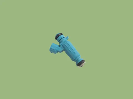
Injector
|
Item |
Specification |
|
|
Coil Resistance (Ω) |
Approximately 9.6 |
|
|
Minimum Injection Time (ms) |
1.8 |
|
|
Fuel Pressure |
bar |
2 ~ 7 |
|
kPa |
200 ~ 700 |
|
|
kgf/cm² |
2.04 ~ 7.14 |
|
|
psi |
29.0 ~ 101.5 |
|
|
Pin |
2 |
|
Description and operation
| Description |
Based on information from various sensors, the ECM can calculate the fuel amount to be injected. The fuel injector is a solenoid-operated valve and the fuel injection amount is controlled by length of injection time. The ECM controls each injector by grounding the control circuit. When the ECM energizes the injector by grounding the control circuit, the circuit voltage should be low (theoretically 0V) and the fuel is injected. When the ECM de-energizes the injector by opening control circuit, the fuel injector is closed and circuit voltage should momentarily peak.
Schematic diagrams
| Circuit Diagram |

Repair procedures
| Inspection |
| 1. |
Turn ignition switch OFF. |
| 2. |
Disconnect injector connector. |
| 3. |
Measure resistance between injector terminals 1 and 2.
|
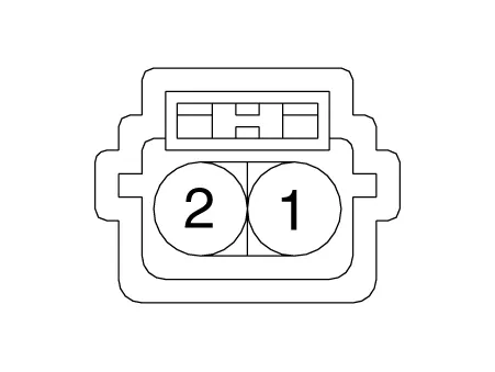
| 4. |
Check that the resistance is within the specification.
|
| Removal |
| 1. |
Release the residual pressure in fuel line. (Refer to “Release Residual Pressure in Fuel Line” in this group). |
| 2. |
Turn the ignition switch OFF and disconnect the battery negative (-) terminal. |
| 3. |
Remove the engine cover. (Refer to Engine And Transaxle Assembly - "Engine Cover") |
| 4. |
Remove the wiring harness after loonsening the mounting bolts. |
| 5. |
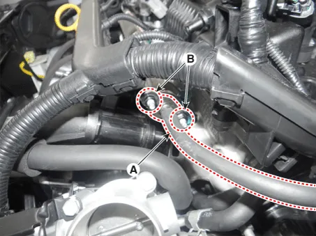
Disconnect the injector connector (A).
|
| 6. |
Remove the PCV hose (A).
|
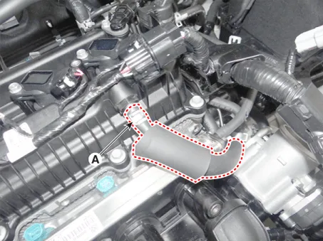
| 7. |
Disconnect the fuel feed tube (A) after loosening the mounting nuts (B).
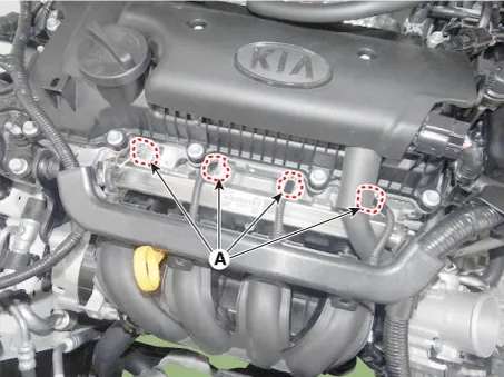
|
| 8. |
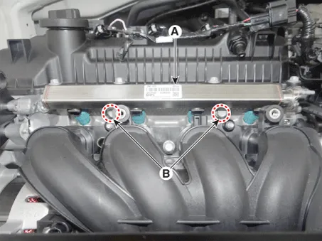
Remove the delivery pipe & injector assembly (A) after loosening the mounting bolts (B).
|
| 9. |
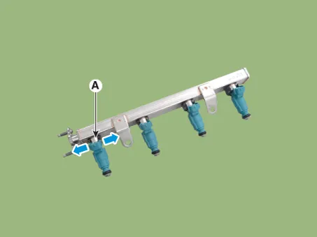
Remove the fixing clip (A), and then separate the injector from the delivery pipe.
|
| Installation |
|

| 1. |
Installation is reverse of removal. |
Specifications Specification Accelerator Position Output Voltage (V) [Vref = 5V] APS1 APS2 C.
Specifications Specification Purge Control Solenoid Valve (PCSV) Item Specification Coil Resistance (Ω) 18.
Other information:
Kia Rio 2017-2023 YB Service Manual: Rear Glass Defogger Switch
Repair procedures Inspection 1. In the body electrical system, failure can be quickly diagnosed by using the vehicle diagnostic system (KDS/GDS). The diagnostic system (KDS/GDS) provides the following information. (1) Self diagnosis : Checking failure and code number (DTC)
Kia Rio 2017-2023 YB Service Manual: Smart Key Diagnostic
Repair procedures Inspection Self Diagnosis With Scan Tool It will be able to diagnose defects of SMART KEY system with KDS/GDS quickly. KDS/GDS can operates actuator forcefully, input/output value monitoring and self diagnosis. The following three features will be major problem in SMART KEY system.
Categories
- Manuals Home
- Kia Rio Owners Manual
- Kia Rio Service Manual
- Motor Driven Power Steering
- Engine Electrical System
- Steering System
- New on site
- Most important about car
