Kia Rio: Engine Control System / Knock Sensor (KS)
Specifications
| Specification |
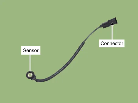
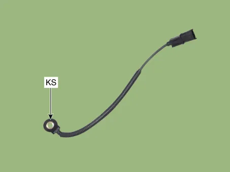
Knock Sensor (KS)
|
Item |
Specification |
|
Resistance(MΩ) |
4.87 |
|
Capacitance (pF) |
950 ~ 1,350 |
|
Type |
Piezo-electricity |
|
Pin |
2 |
Description and operation
| Description |
Knocking is a phenomenon characterized by undesirable vibration and noise and can cause engine damage. Knock Sensor (KS) is installed on the cylinder block and senses engine knocking.
When knocking occurs, the vibration from the cylinder block is applied as pressure to the piezoelectric element. At this time, this sensor transfers the voltage signal higher than the specified value to the ECM and the ECM retards the ignition timing. If the knocking disappears after retarding the ignition timing, the ECM will advance the ignition timing. This sequential control can improve engine power, torque and fuel economy.
Schematic diagrams
| Circuit Diagram |

Repair procedures
| Removal |
| 1. |
Turn ignition switch OFF and disconnect the battery negative (-) terminal. |
| 2. |
Remove the intake manifold. (Refer to Engine Mechanical System - "Intake Manifold") |
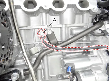
| 3. |
Remove the installation bolt (A), and then remove the sensor from the cylinder block.
|
| Installation |
|

| 1. |
Installation is reverse of removal. |
Specifications Specification Camshaft Position Sensor (CMPS) Item Specification Type Hall effect type Output Pulse (V) 0 ~ 5 Air Gap [mm (in.
Specifications Specification Heated Oxygen Sensor (HO2S) HO2S [Bank 1/Sensor 1] Item Specification Heater Resistance (Ω) Approximately 9.
Other information:
Kia Rio 2017-2023 YB Service Manual: Overhead Console Lamp
Repair procedures Inspection 1. Remove the overhead console lamp assembly then check for continuity between terminals. If the continuity is not as specified, replace the map lamp switch. Removal 1.
Kia Rio 2017-2023 YB Service Manual: Cluster Ionizer (FATC only)
Description and operation Description The cluster ionizer helps to clean up odors in the vehicle or from the air-conditioner system. When the ignition switch ON, the inoizer runs a "CLEAN" mode and then a "ION" mode, switching every about 15 minutes.
Categories
- Manuals Home
- Kia Rio Owners Manual
- Kia Rio Service Manual
- Emission Control System
- Motor Driven Power Steering
- Maintenance Schedule
- New on site
- Most important about car
