Kia Rio: Body Electrical System / AVN System
Components and components location
| Component Location |
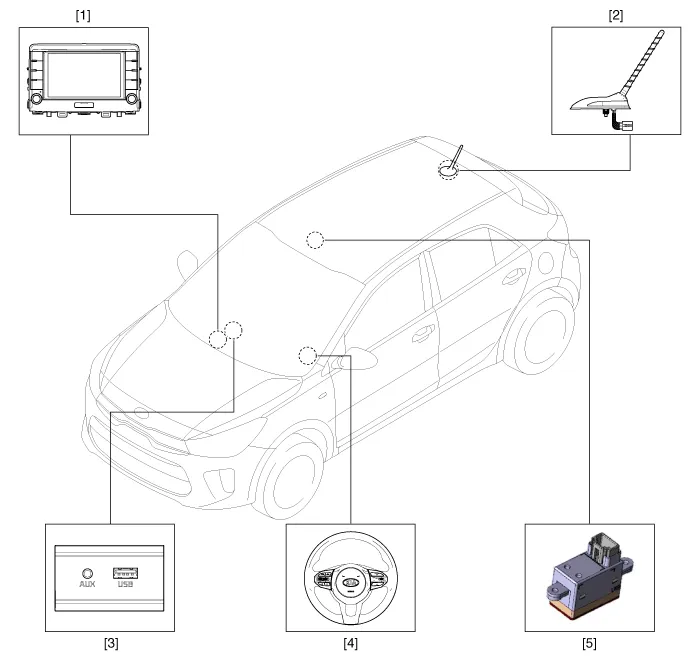
| 1 . AVN head unit 2. Roof antenna (Radio+GPS+DAB) 3 . Multimedia jack |
4 . Steering wheel remote control
(SWRC) 5 . Hands-free mic (Built-in overhead console) |
Description and operation
| Description |
AVN system
The AVN system simplifies system manipulation and by unifying the vehicle information and user information displays, improves information search and operation experience.
The system is basically composed of a keyboard for the operation of combined function, LCD monitor, a head unit with Bluetooth handsfree calling, voice recognition and navigation, music amplifier and the media unit that connects with other external devices.
| 1. |
Simplification of user interface : the multimedia and car information are displayed on the monitor. |
| 2. |
Up-to-date technologies integrated :
|
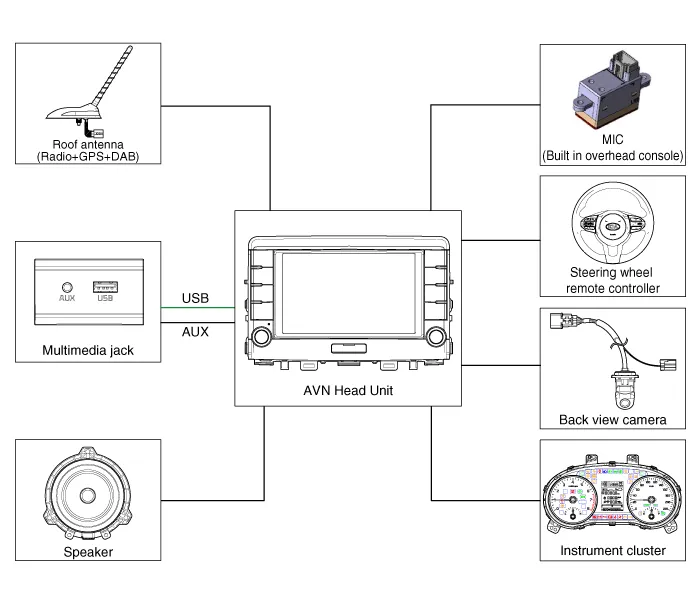
System Block Diagram
Limitations Of The Navigation system
GPS Signal Reception State
As the GPS satellite frequency is received/transmitted in straight lines, reception may not work if an object is placed on or near the GPS antenna or when travelling in the following environment:
| • |
Tunnels |
| • |
Basement parking structures |
| • |
Underneath an overpass |
| • |
Roads within forested areas |
| • |
Areas near high rise buildings |
| • |
Roads within canyons |
Vehicle Position Display
| 1. |
If multipass errors occur due to reflections from buildings or related causes, the current position mark on the navigation may differ from the actual position of the vehicle. |
| 2. |
The position of the vehicle on the navigation may be different from the actual position if the vehicle is in the following location or driving condition. In this case, drive for a short period of time to automatically correct vehicle location according to map matching or GPS information. (It may take several minutes in certain cases.)
|
Route Guidance
Suitable route guidance may not occur due to search conditions or driving position.
| • |
Guidance to go straight may be given while driving on a straight road. |
| • |
Guidance may not be given after turning at an intersection. |
| • |
Proper guidance may not be given at certain intersections. |
| • |
A route guidance signaling entrance into a no entry zone may occur (No entry zone, road under construction, etc.). |
| • |
Guidance may be given to a location near the actual destination if roads to the actual destination do not exist or are too narrow. |
| • |
Wrong voice guidance may be given if the vehicle deviates from the designated route (e.g. If it turned at an intersection wherein the navigation guided to go straight.). |
| • |
The route guidance may not be provided in case of missing or incorrect map data. |
Route Re-calculation
The following phenomena may occur after conducting route recalculation.
| • |
Guidance may be given to a different position from the current position if the vehicle was turning at an intersection. |
| • |
Route recalculation may take longer when driving under high speeds. |
| • |
A route guidance signaling for a U-Turn in a No U-Turn zone may occur. |
| • |
In some cases, a route guidance may signal the driver to enter a no entry zone (No entry zone, road under construction, etc.). |
| • |
Guidance may be given to a location near the actual destination if roads to the actual destination do not exist or are too narrow. |
| • |
Wrong voice guidance may be given if the vehicle deviates from the designated route (e.g. If it turns at an intersection wherein the navigation guided to go straight.). |
Repair procedures Inspection Check if the auto light control operates like a timing chart shown below. Tail lamp output and head lamp (Low) output is controlled based on the auto light sensor's input (illumination intensity) when the Auto Light Switch in Multi-Function Switch is turned ON, and the vehicle is in IGN1 or IGN2 ON Mode.
Components and components location Components Connector Pin Information No. Connector A Connector B 1 Rear door left speaker (+) - 2 Rear door left speaker (-) MIC (+) 3 - - 4 - - 5 - Antenna power 6 Camera Power Illumination (+) 7 Camera Video Multimedia-CAN (High) 8 - - 9 - ALT Left_output (-) 10 AUX Audio right_input Battery (+) 11 AUX Detect Battery (+) 12 Steering wheel remote controller Ground 13 Front door left speaker (+) Ground 14 Front door left speaker (-) MIC (Ground) 15 Front door right speaker (-) MIC (-) 16 Front door right speaker (+) - 17 - - 18 - - 19 - Illumination (-) 20 Camera Power_Ground Multimedia-CAN (Low) 21 Camera Video_Ground - 22 - ACC 23 - - 24 AUX Audio left_input - 25 AUX Audio ground Reverse 26 Steering wheel remote controller (Ground) Door open 27 Rear door right speaker (-) Door unlock_status 28 Rear door right speaker (+) Manual parking 29 - 'P' Position 30 - Auto light 31 - - 32 - - 33 Camera shield_Ground IGN1 34 - - 35 - - 36 - 37 - 38 Vehicle speed Repair procedures Removal • Be careful not to scratch the center fascia upper panel and related parts.
Other information:
Kia Rio 2017-2023 YB Service Manual: Antenna Coil
Repair procedures Removal 1. Disconnect the negative (-) battery terminal. 2. Remove the crash pad lower panel. (Refer to Body - "Crash Pad Lower Panel") 3. Remove the steering column upper and lower shroud panel.
Kia Rio 2017-2023 YB Service Manual: Rain Sensor
Components and components location Components Schematic diagrams Circuit Diagram Description and operation Description Integrated Rain Sensor Integrated rain sensor (A) controls three systems: front wiper, auto-light, and central air conditioner.
Categories
- Manuals Home
- Kia Rio Owners Manual
- Kia Rio Service Manual
- Suspension System
- Maintenance
- Maintenance Schedule
- New on site
- Most important about car
