
Kia Rio: AVN System / AVN Antenna
Components and components location
| Components |
| [Roof Antenna (Radio + GPS +DAB)] |
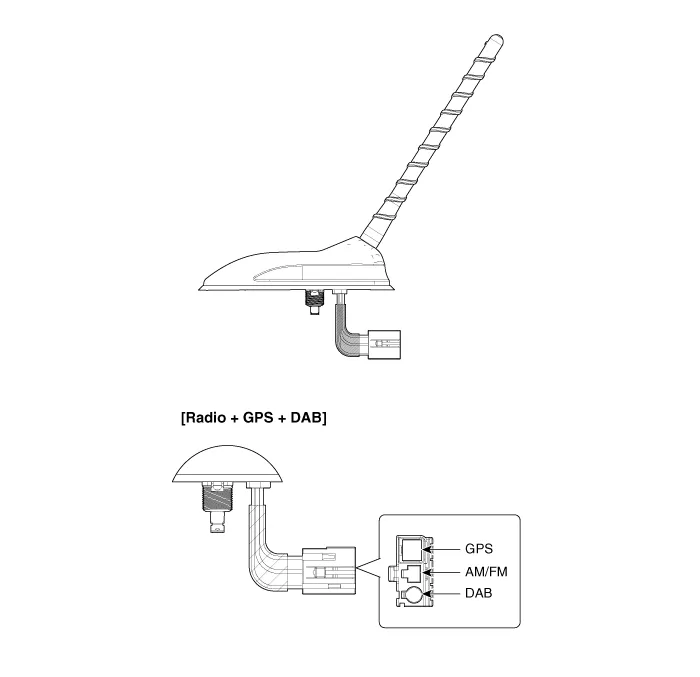
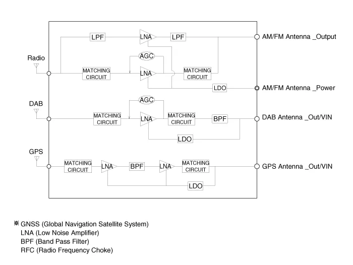
Repair procedures
| Removal |
Roof antenna
| 1. |
Disconnect the negative (-) battery terminal. |
| 2. |
Remove the roof trim assembly. (Refer to Body - "Roof Trim Assembly") |
| 3. |
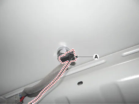
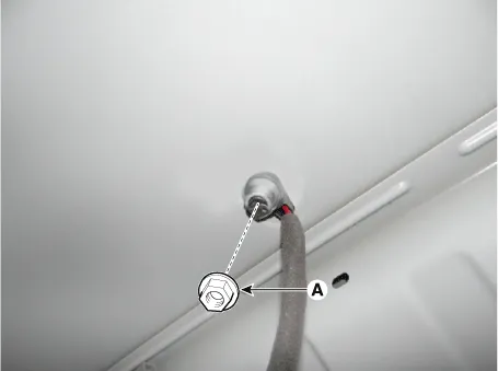
Disconnect the roof antenna power connector (A).
|
| 4. |
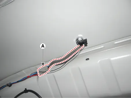
Disconnect the radio antenna connector (A).
|
| 5. |
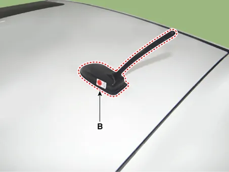
Remove the roof antenna (B) after loosening a nut (A).
|
| Installation |
Roof anenna
| 1. |
Install the roof antenna. |
| 2. |
Connect the roof antenna power connector and radio antenna connectors. |
| 3. |
Install the roof trim assembly. |
| 4. |
Connect the negative (-) battery terminal.
|

Repair procedures Inspection Troubleshooting of the speakers When handling the speakers : • Do not cause shock to the speakers by dropping or throwing them.
Components and components location Components 1. Left Remote Control Switch (Audio + Hands free + Voice) 2. Right Remote Control Switch (Cruise+Trip Computer) Schematic diagrams Circuit Diagram [Audio] [Audio + Bluetooth] [Audio + Bluetooth + Voice] [Trip] [Trip + ACC (2 Button)] [Trip + ACC + SLD (2 Button)] [Trip + ACC (4 Button)] [Trip + ACC + SLD (4 Button)] Repair procedures Removal 1.
Other information:
Kia Rio 2017-2023 YB Service Manual: Room Lamp
Repair procedures Removal • Put on gloves to prevent hand injuries. • When removing with a flat-tip screwdriver or remover, wrap protective tape around the tools to prevent damage to componen
Kia Rio 2017-2023 YB Service Manual: Climate Control Air Filtar
Description and operation Description The climate control air filter is located in the bower unit. It eliminates foreign materials and odor. The particle filter performs a role as an odor filter as well as a conventional dust filter to ensure comfortable interior environment.
Categories
- Manuals Home
- Kia Rio Owners Manual
- Kia Rio Service Manual
- Engine Mechanical System
- Steering System
- Brake System
- New on site
- Most important about car
