
Kia Rio: Fuel Delivery System / Fuel Pressure Regulator
Repair procedures
| Removal |
| 1. |
Remove the fuel pump. (Refer to Fuel Delivery System - "Fuel Pump") |
| 2. |
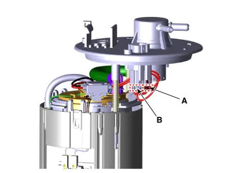
Disconnect the fuel pump motor connector (A) and fuel sender connector (B).
|
| 3. |
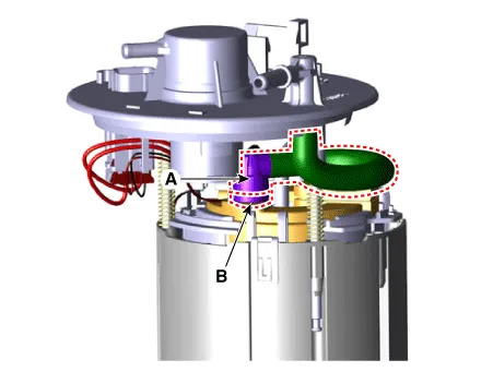
Disconnect the fuel feed tube quick-connector (A) after removing the fixing clip (B).
|
| 4. |
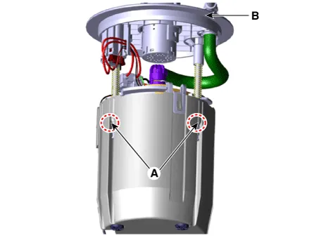
Remove the cushion pipe fixing clip (A), and then separate the head assembly (B) from reservoir cup.
|
| 5. |
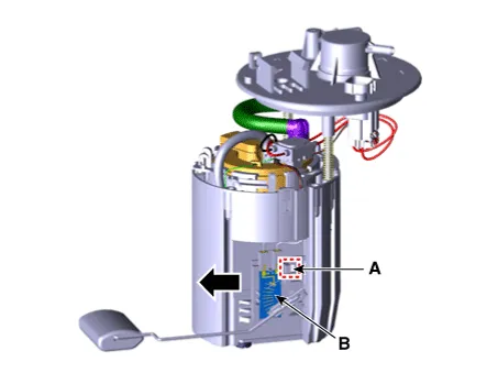
Press the fixing hook (A) with a driver and then remove fuel sender in the arrow direction.
|
| 6. |
Remove the reservoir-cup (B) after releasing the fixing hooks (A).
|
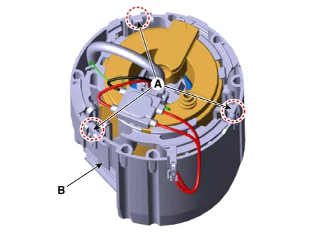
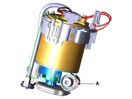
| 7. |
Remove the fuel pressure regulator fixing clip (A).
|
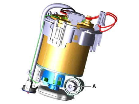
| 8. |
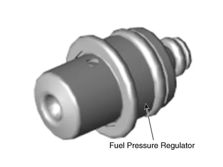
Remove the fuel pressure regulator (A) from the fuel filter.
|
| Installation |
| 1. |
Install in the reverse order of removal. |
Repair procedures Removal 1. Remove the fuel pump. (Refer to Fuel Delivery System - "Fuel Pump") 2.
Repair procedures Removal 1. Open the fuel filler door and then remove the filler-neck mounting bolts (A). Filler-neck assembly mounting bolt: 7.
Other information:
Kia Rio 2017-2023 YB Service Manual: Air Conditioning System
General safety information and caution Instructions When Handling Refrigerant 1. R-134a liquid refrigerant is highly volatile. A drop on the skin of your hand could result in localized frostbite. When handling the refrigerant, be sure to wear gloves.
Kia Rio 2017-2023 YB Service Manual: Condenser
Repair procedures Inspection 1. Check the condenser fins for clogging and damage. If clogged, clean them with water, and blow them with compressed air. If bent, gently bend them using a screwdriver or pliers. 2.
Categories
- Manuals Home
- Kia Rio Owners Manual
- Kia Rio Service Manual
- Body Electrical System
- Maintenance
- Suspension System
- New on site
- Most important about car
