Kia Rio: Engine Oil and Filter / Fuel Filter (For Diesel engine only)
Repair procedures
| Replacement |
| 1. |
Turn ignition switch OFF and disconnect the negative (-) battery terminal. |
| 2. |
Remove the battery. (Refer to Engine Electrical System - "Battery") |
| 3. |
Remove the ECM. (Refer to Engine Control / Fuel System - "ECM") |
| 4. |
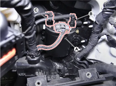
Disconnect the water sensor heater connector (A). |
| 5. |
Disconnect the fuel inlet tube (B) quick-connector and the fuel outlet tube (C) quick-connector.
|
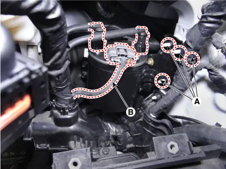
| 6. |
Remove the fuel filter assembly (B) after loosening the mounting nuts (A).
|
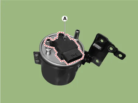
| 7. |
Remove the fuel heater & water sensor (A) after loosening the mounting bolt.
|
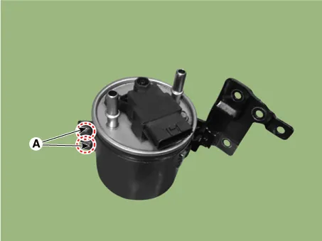
| 8. |
Remove the fuel filter assembly from the bracket after removing the bracket bolts (A), replace it with a new one, and then install the fuel filter assembly in accordance with reverse of above steps.
|

| 9. |
Bleed air in low pressure fuel circuit. (Refer to Engine Control / Fuel System - "Bleeding air procedure in low pressure fuel circuit") |
| 10. |
Start the engine and check that there is any leak on the low pressure fuel circuit including the fuel filter. |
| 11. |
Install in the reverse order of removal. |
Repair procedures Inspection Automatic Transaxle Fluid (ATF) Level Check 1. Place the vehicle on a level ground. 2.
Repair procedures Inspection Visually check the fuel lines for cracks, leakage, loose connections, deformation or tank band looseness.
Other information:
Kia Rio 2017-2023 YB Service Manual: License Lamps
Repair procedures Removal 1. Disconnect the negative (-) battery terminal. 2. Remove the license lamp assembly (A) after pressing the locking pin. 3. Disconnect the license lamp connector (A).
Kia Rio 2017-2023 YB Service Manual: Power Windows
Components and components location Component Location 1. Driver power window switch 2. Assist power window switch 3. Rear power window switch 4. Front window motor 5. Rear window motor Description and operation Safety Function of Power Window When driver door power win
Categories
- Manuals Home
- Kia Rio Owners Manual
- Kia Rio Service Manual
- Brake System
- Maintenance
- Engine Electrical System
- New on site
- Most important about car
