Kia Rio: Automatic Transaxle Control System / Shift Lever
Components and components location
| Components |
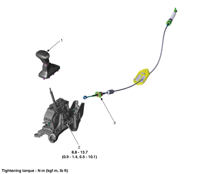
| 1. Shift lever knob & boots
2. Shift lever assembly |
3. Shift cable assembly |
Repair procedures
| Removal |
| 1. |
Shift the gear to "N". |
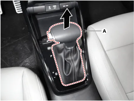
| 2. |
Remove the knob (A) by pulling it in the direction of arrow after removing the boots from the console upper cover.
|
| 3. |
Remove the floor console assembly. (Refer to Body - "Floor Console Assembly") |
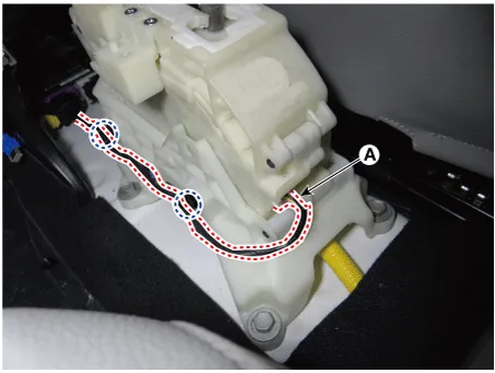
| 4. |
Disconnect the main connector (A) and then remove the wiring mounting clips from the shift lever.
|
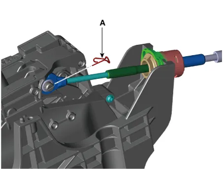
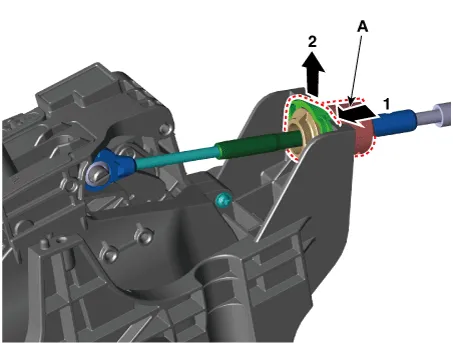
| 5. |
Remove the shift cable from the shift lever pim after removing the snap pin (A).
|
| 6. |
Remove the cable socket (A) from the shift lever.
|
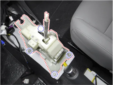
| 7. |
Remove the shift lever after loosening the bolts.
|
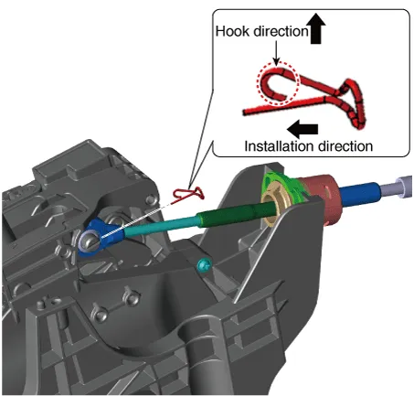
| Installation |
| 1. |
Install in the reverse order of removal. |
|


Description and operation Description Detect the position of shift lever through the contact switch. Operation Table Schematic diagrams Circuit Diagram Repair procedures Inspection 1.
Components and components location Components 1. Shift lever knob & boots 2. Shift lever assembly 3. Shift cable assembly Repair procedures Removal 1.
Other information:
Kia Rio 2017-2023 YB Service Manual: Smart Key Diagnostic
Repair procedures Inspection Self Diagnosis With Scan Tool It will be able to diagnose defects of SMART KEY system with KDS/GDS quickly. KDS/GDS can operates actuator forcefully, input/output value monitoring and self diagnosis. The following three features will be major problem in SMART KEY system.
Kia Rio 2017-2023 YB Service Manual: Heater & A/C Control Unit (FATC)
Components and components location Components Connector Pin Function No. Connector A Connector B 1 Battery ⁻ 2 ISG battery (+) ⁻ 3 Illumination (+) ⁻
Categories
- Manuals Home
- Kia Rio Owners Manual
- Kia Rio Service Manual
- Heating,Ventilation, Air Conditioning
- Clutch System
- Emission Control System
- New on site
- Most important about car
