Kia Rio: Automatic Transaxle Control System / Inhibitor Switch
Description and operation
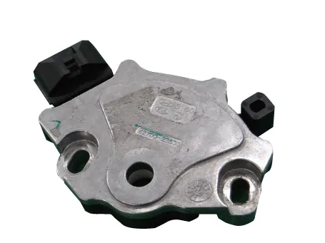
| Description |
Detect the position of shift lever through the contact switch.
Operation Table

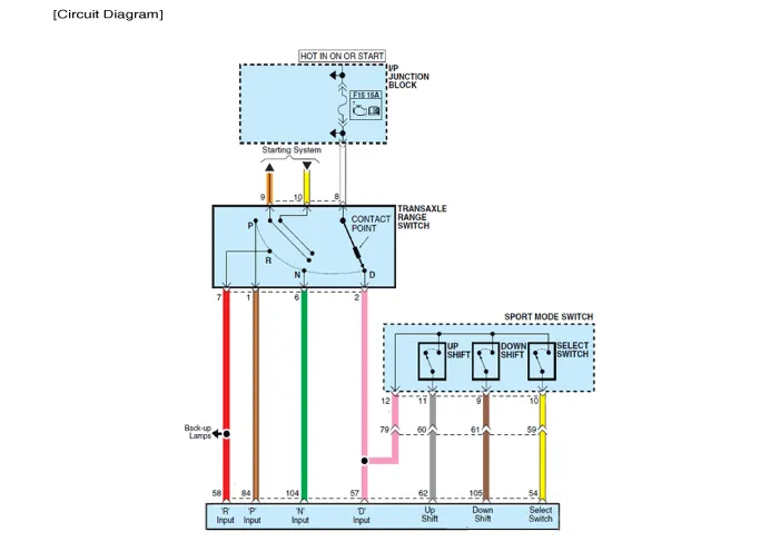
Schematic diagrams
| Circuit Diagram |
Repair procedures
| Inspection |
| 1. |
Check the condition of connector.
|
| 2. |
Check the inhibitor switch circuit signal.
|
| Removal |
| 1. |
Shift the gear to "N". |
| 2. |
Remove the air cleaner. (Refer to Engine Mechanical System - "Air cleaner") |
| 3. |
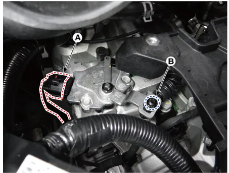
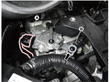
Disconnect the inhibitor switch connector (A) and loosen the shift cable mounting nut (B).
|
| 4. |
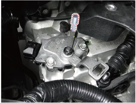
Remove the inhibitor switch (B) after removing the manual control lever (A).
|

| Installation |
| 1. |
Check that the gear is shifted to "N". |
| 2. |
Install the manual control lever (A) after installing the inhibitor switch (B).
|

| 3. |
Align the hole in the manual control lever with the "N" position hole of the inhibitor switch and then insert the SST (09480-A3800).
|
| 4. |
Tighten the manual control lever mounting nut (A).
|
| 5. |
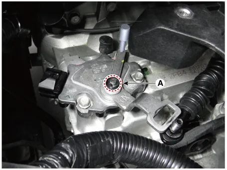
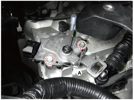
Tighten the inhibitor switch mounting bolts (A).
|
| 6. |
Remove the SST (09480-A3800).
|
| 7. |
Connect the inhibitor switch connector (A). |
| 8. |
Tighten the nut (B) to the specified torque after removing free play by pushing the shift cable in the direction of the arrow
|
| 9. |
Install the air cleaner. (Refer to Engine Mechanical System - "Air cleaner") |
Specifications Specification Item Specification Type Hall effect sensor Current 22 mA (Max) Output voltage High : 4.
Components and components location Components 1. Shift lever knob & boots 2. Shift lever assembly 3. Shift cable assembly Repair procedures Removal 1.
Other information:
Kia Rio 2017-2023 YB Service Manual: Instrument Cluster
Components and components location Components [Standard Type ("3.5")] [Supervision Type ("3.5")] Connector Pin Information Connector A No.
Kia Rio 2017-2023 YB Service Manual: Power Door Mirror Actuator
Components and components location Components 1. Side repeater lamp Repair procedures Inspection 1. Disconnect the negative (-) battery terminal. 2. Remove the front door quadrant inner cover (A).
Categories
- Manuals Home
- Kia Rio Owners Manual
- Kia Rio Service Manual
- Brake System
- Coolant
- Maintenance Schedule
- New on site
- Most important about car
