Kia Rio: Manual Transaxle Control System / Shift Lever
Components and components location
| Components |
|
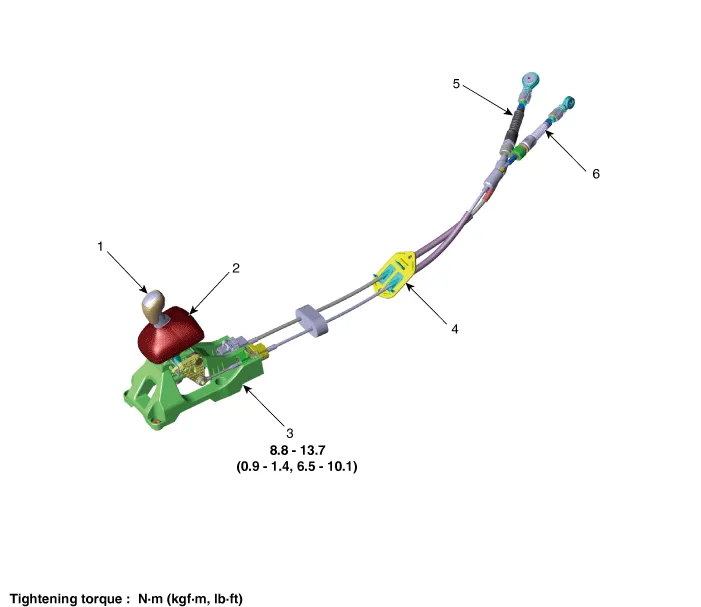
1. Knob 2. boots 3. Shift lever assembly |
4. Retainer 5. Shift cable 6. Select cable |
Repair procedures
| Removal |
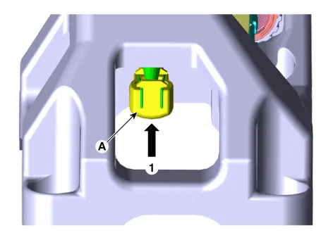
| 1. |
Remove the knob by pulling it in the direction of upward after removing the boots from the console upper cover. |
| 2. |
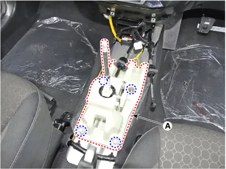
Remove the floor console assembly. (Refer to Body - "Floor Console Assembly") |
| 3. |
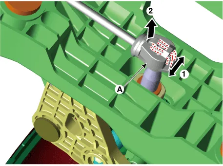
Remove the snap pin (A) and then remove the select cable from the shift lever pin.
|

| 4. |
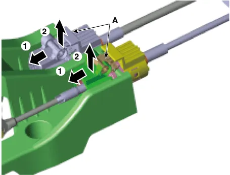
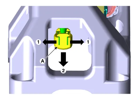
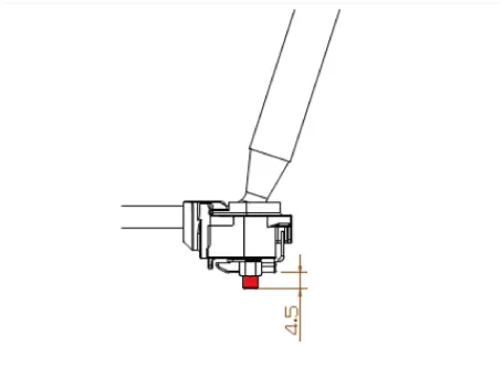
Remove the cable sockets (A) from the shift lever.
|
| 5. |
Loosen the shift lever mounting bolts (A).
|
| 6. |
Remove the shift cable (A) from the shift lever. [A Type]
[B Type]
|
| Installation |
| 1. |
Install in the reverse order of removal.
|


| Inspection |
| 1. |
Check for proper operation of control shaft lever when operated (1st, 2nd, 3rd, 4th, 5th, 6th, R gear). |
| 2. |
When the shift lever is engaged to "R", check that the skirt is in proper position. |
| 3. |
If the gear feels stiff, adjust the control cable length again. (Refer to Control Cable - "Installation") |
Components and components location Components Location 1. Control shaft complete Repair procedures Removal 1. Shift the gear to "neutral".
Components and components location Components 1. Knob 2. boots 3. Shift lever assembly 4. Retainer 5.
Other information:
Kia Rio 2017-2023 YB Service Manual: Condenser
Repair procedures Inspection 1. Check the condenser fins for clogging and damage. If clogged, clean them with water, and blow them with compressed air. If bent, gently bend them using a screwdriver or pliers. 2.
Kia Rio 2017-2023 YB Service Manual: Heater & A/C Control Unit (FATC)
Components and components location Components Connector Pin Function No. Connector A Connector B 1 Battery ⁻ 2 ISG battery (+) ⁻ 3 Illumination (+) ⁻
Categories
- Manuals Home
- Kia Rio Owners Manual
- Kia Rio Service Manual
- Cooling System
- Steering System
- Brake System
- New on site
- Most important about car
