
Kia Rio: Power Door Locks / Power Door Lock Switch
Repair procedures
| Removal |
|

| 1. |
Disconnect the negative (-) battery terminal. |
| 2. |
Remove the crash pad center lower panel. (Refer to Body - "Crash Pad Center Panel") |
| 3. |
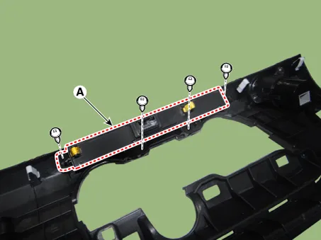
Remove the hazard warning lamp switch (A) after loosening the mounting screws.
|
| Installation |
| 1. |
Install the hazard warning lamp switch. |
| 2. |
Install the crash pad center lower panel. |
| 3. |
Connect the negative (-) battery terminal. |
| Inspection |
| 1. |
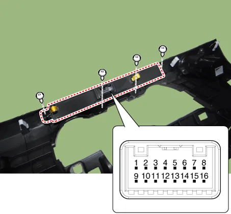
Check for continuity between the terminals. If there is an abnormality, replace the switch.
|

Components and components location Components 1. Door lock/unlock knob cable 2. Door latch assembly Repair procedures Inspection • When removing with a flat-tip screwdriver or remover, wrap protective tape around the tools to prevent damage to components.
Components and components location Component Location 1. Power door mirror 2. Power door mirror switch 3. Power folding mirror switch
Other information:
Kia Rio 2017-2023 YB Service Manual: Immobilizer System
Schematic diagrams Circuit Diaram Description and operation Description The immobilizer system will disable the vehicle unless the proper ignition key is used, in addition to the currently available anti-theft systems such as car alarms, the immobilizer system aims to drastically reduce the rate of auto theft.
Kia Rio 2017-2023 YB Service Manual: License Lamps
Repair procedures Removal 1. Disconnect the negative (-) battery terminal. 2. Remove the license lamp assembly (A) after pressing the locking pin. 3. Disconnect the license lamp connector (A).
Categories
- Manuals Home
- Kia Rio Owners Manual
- Kia Rio Service Manual
- Brake System
- Filler-Neck Assembly
- Restraint
- New on site
- Most important about car
