Kia Rio: Lighting System / Overhead Console Lamp
Repair procedures
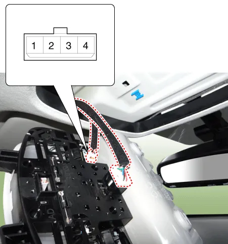
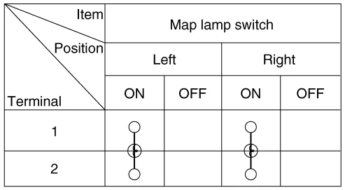
| Inspection |
| 1. |
Remove the overhead console lamp assembly then check for continuity between terminals. If the continuity is not as specified, replace the map lamp switch.
|
| Removal |
| 1. |
Disconnect the negative (-) battery terminal. |
| 2. |
Remove the two mounting screws. And then remove the overhead console (A).
|

| 3. |
Remove the overhead console after disconnecting the connectors (A).
|

| Installation |
| 1. |
Install the overhead console lamp after connecting the connector. |
| 2. |
Install the lens after tightening 2 screws. |
Repair procedures Removal 1. Disconnect the negative (-) battery terminal. 2. Detach the vanity lamp (A) using a flat-tip screwdriver.
Repair procedures Inspection 1. Check for continuity between terminals. If the continuity is not as specified, replace the hazard lamp switch.
Other information:
Kia Rio 2017-2023 YB Service Manual: Lane Departure Warning System (LDWS)
Components and components location Components 1. LDWS ON/OFF switch 2. Instrument cluster 3. LDWS unit (MFC) ※ MFC : Multi Function Camera – Function : LDWS, HBA, AEB Description and operation Description System block diagram Components of LDWS
Kia Rio 2017-2023 YB Service Manual: Rear Glass Defogger Switch
Repair procedures Inspection 1. In the body electrical system, failure can be quickly diagnosed by using the vehicle diagnostic system (KDS/GDS). The diagnostic system (KDS/GDS) provides the following information. (1) Self diagnosis : Checking failure and code number (DTC)
Categories
- Manuals Home
- Kia Rio Owners Manual
- Kia Rio Service Manual
- Motor Driven Power Steering
- Normal Condition
- Brake System
- New on site
- Most important about car
