Kia Rio: Automatic Transaxle Control System / Output Speed Sensor
Specifications
| Specification |
|
Item |
Specification |
|
Type |
Hall effect sensor |
|
Current |
22 mA (Max) |
|
Output voltage |
High : 4.8 V - 5.2 V |
|
Low : Below 0.8 |
Description and operation
| Description |
| • |
Measures the rate of rotation of the output shaft inside the transaxle and delivers the readings to the TCM. |
| • |
The sensor provides critical input data used in feedback control, torque converter clutch control, gear setting control, line pressure control, clutch activation pressure control, and sensor fault analysis.
|
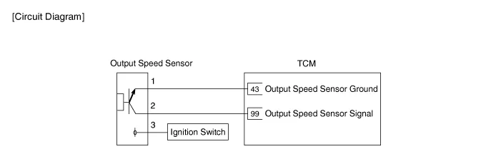
Schematic diagrams
| Circuit Diagram |
Repair procedures
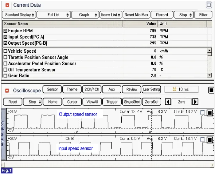
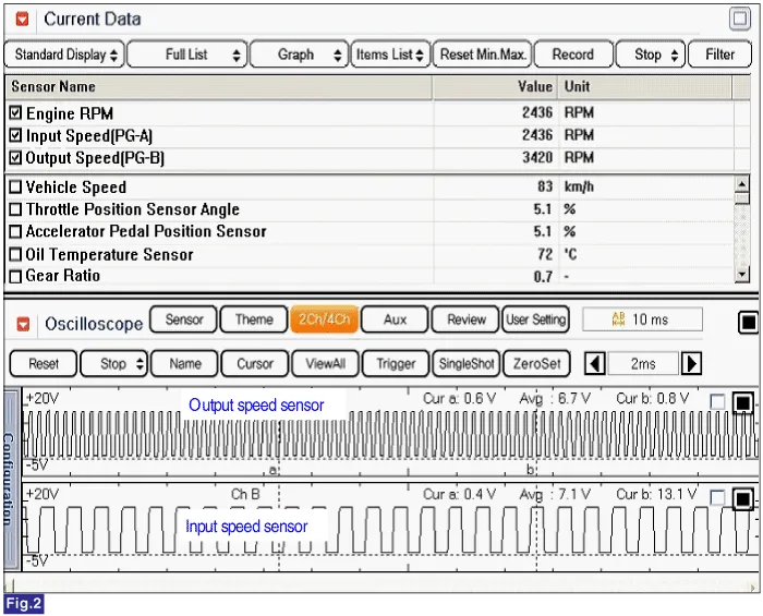
| Inspection |
| 1. |
Check the signal waveform of output speed sensor using the KDS/GDS. |
Low speed
High speed
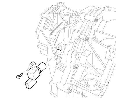
| Removal |
| 1. |
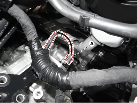
Disconnect the output speed sensor connector (A).
|
| 2. |
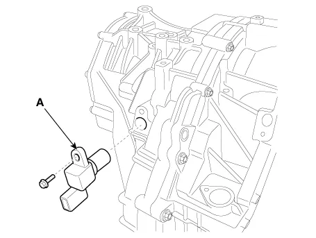
Remove the output speed sensor (A).
|
| Installation |
| 1. |
Install in the reverse order of removal. |
Specifications Specification Item Specification Type Hall effect sensor Current 22 mA (Max) Output voltage High : 4.
Description and operation Description Detect the position of shift lever through the contact switch. Operation Table Schematic diagrams Circuit Diagram Repair procedures Inspection 1.
Other information:
Kia Rio 2017-2023 YB Service Manual: Headlamps
Description and operation Description BI-FUNCTION 1. Definition – A headlamp with integrated functions of high and low beam – The light is controlled by rotating the shield inserted to the lens.
Kia Rio 2017-2023 YB Service Manual: Windshield Wiper-Washer Switch
Repair procedures Removal [BCM Type] 1. Disconnect the negative (-) battery terminal. 2. Remove the steering wheel. (Refer to Steering System - "Steering Wheel") 3.
Categories
- Manuals Home
- Kia Rio Owners Manual
- Kia Rio Service Manual
- Engine Mechanical System
- Engine Electrical System
- Steering System
- New on site
- Most important about car
