Kia Rio: Automatic Transaxle Control System / Input Speed Sensor
Specifications
| Specification |
|
Item |
Specification |
|
Type |
Hall effect sensor |
|
Current |
22 mA (Max) |
|
Output voltage |
High : 4.8 V - 5.2 V |
|
Low : Below 0.8 |
Description and operation
| Description |
| • |
Measures the rate of rotation of the input shaft inside the transaxle and delivers the readings to the TCM. |
| • |
The sensor provides critical input data used in feedback control, torque converter clutch control, gear setting control, line pressure control, clutch activation pressure control, and sensor fault analysis.
|
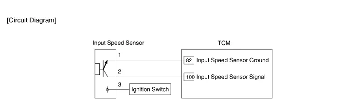
Schematic diagrams
| Circuit Diagram |
Repair procedures
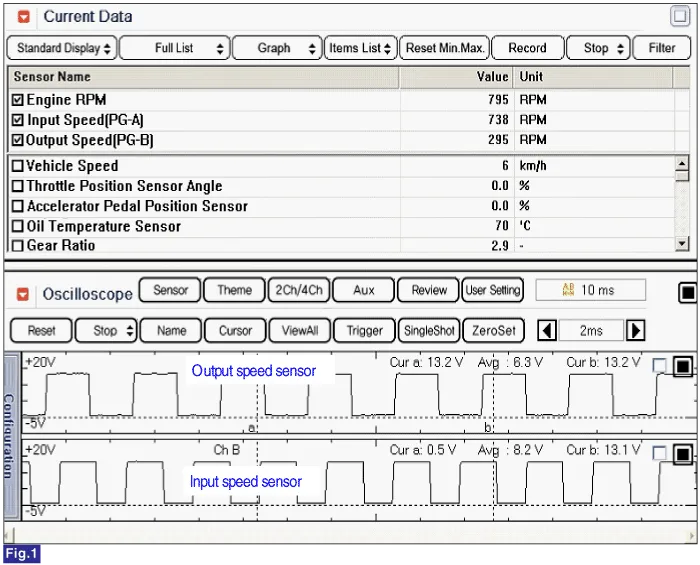
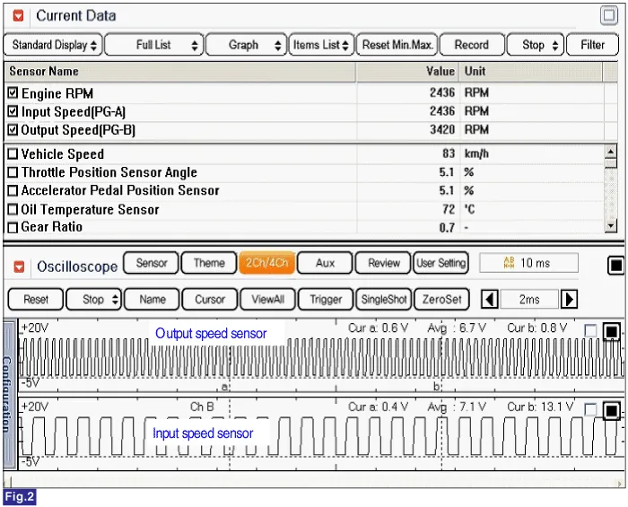
| Inspection |
| 1. |
Check the signal waveform of input speed sensor using the KDS/GDS. |
Low speed
High speed
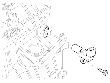
| Removal |
| 1. |
Remove the air cleaner. (Refer to Engine Mechanical System - "Air cleaner") |
| 2. |
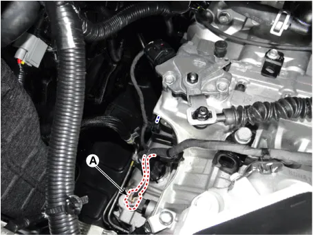
Disconnect the input speed sensor connector (A).
|
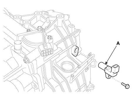
| 3. |
Remove the input speed sensor (A) after loosening the bolt.
|
| Installation |
| 1. |
Install in the reverse order of removal. |
Specifications Specification Item Specification Type *NTC thermistor Temp.
Specifications Specification Item Specification Type Hall effect sensor Current 22 mA (Max) Output voltage High : 4.
Other information:
Kia Rio 2017-2023 YB Service Manual: Power Window Switch
Components and components location Components Driver Power Window Switch Connector Pin Information [Front / Rear Driver Safety - Auto Up/Down] [LHD] No. Description No. Description 1 Front right power window (Up) 10
Kia Rio 2017-2023 YB Service Manual: Seat Heater Switch
Components and components location Components 1. Driver side seat heater switch 2. Passenger side seat heater switch Description and operation Description Seat Heater Smart Control Technology • To prevent low temperature burn, seat heater temperature will autom
Categories
- Manuals Home
- Kia Rio Owners Manual
- Kia Rio Service Manual
- Maintenance
- Coolant
- Timing Chain
- New on site
- Most important about car
