Kia Rio: Automatic Transaxle Control System / Transaxle Oil Temperature Sensor
Specifications
| Specification |
|
Item |
Specification |
|
Type |
*NTC thermistor |
|
Temp.[(°C)°F] / Resistance (kΩ) |
(-40)-40 / 139.5 |
|
(-20)-4.0 / 47.4 |
|
|
(0)32.0 / 18.6 |
|
|
(20)68.0 / 8.1 |
|
|
(40)104.0 / 3.8 |
|
|
(60)140.0 / 1.98 |
|
|
(80)176.0 / 1.08 |
|
|
(100)212.0 / 0.63 |
|
|
(120)248.0 / 0.38 |
|
|
(140)284.0 / 0.25 |
|
|
(160)320.0 / 0.16 |
*NTC : Negative Temperature Coefficient
Description and operation
| Description |
| • |
The sensor used is a thermistor (NTC) in which resistance changes with temperature variation. |
| • |
Oil temperature sensor is installed on the valve body integrated with a main harness.
|
Functions
| • |
Transaxle oil temperature sensor monitors the temperature of ATF and conveys the readings to TCM. |
| • |
Data produced by this sensor is used to identify torque converter clutch activation and deactivation zones within the low temperature and high temperature range and to compensate hydraulic pressure levels during gear changes. |
Schematic diagrams
| Circuit Diagram |

Repair procedures
| Inspection |
| 1. |
Switch "OFF" ignition. |
| 2. |
Remove the air cleaner. (Refer to Engine Mechanical System - "Air cleaner") |
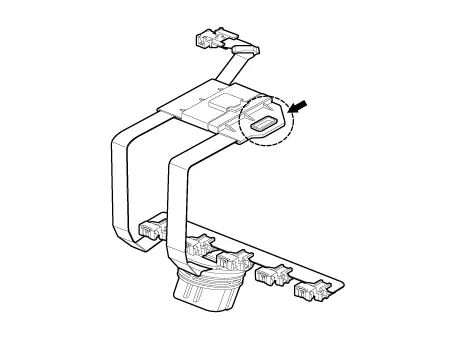
| 3. |
Disconnect the main connector (A).
|

| 4. |
Measure the resistance between + terminal (6) and - terminal (5). |
| 5. |
Check that the resistance is within the specification. |
|
Item |
Specification |
|
Type |
*NTC thermistor |
|
Temp.[(°C)°F] / Resistance (kΩ) |
(-40)-40 / 139.5 |
|
(-20)-4.0 / 47.4 |
|
|
(0)32.0 / 18.6 |
|
|
(20)68.0 / 8.1 |
|
|
(40)104.0 / 3.8 |
|
|
(60)140.0 / 1.98 |
|
|
(80)176.0 / 1.08 |
|
|
(100)212.0 / 0.63 |
|
|
(120)248.0 / 0.38 |
|
|
(140)284.0 / 0.25 |
|
|
(160)320.0 / 0.16 |
*NTC : Negative Temperature Coefficient
| Removal |
| 1. |
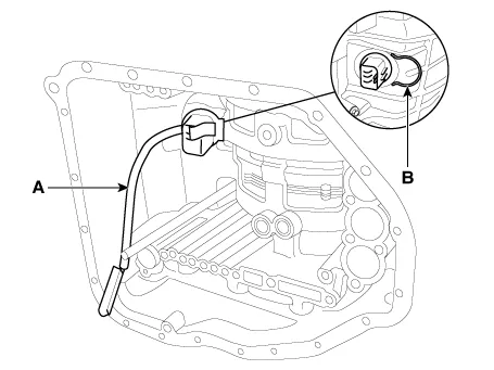
Remove the valve body assembly. (Refer to Hydraulic System - "Valve Body") |
| 2. |
Remove the main harness (A) after removing the clip (B).
|
| Installation |
| 1. |
Install in the reverse order of removal. |
Description and operation Description The module receives and processes signals from various sensors and implements a wide range of transaxle controls to ensure optimal driving conditions for the driver.
Specifications Specification Item Specification Type Hall effect sensor Current 22 mA (Max) Output voltage High : 4.
Other information:
Kia Rio 2017-2023 YB Service Manual: Hazard Lamp Switch
Repair procedures Inspection 1. Check for continuity between terminals. If the continuity is not as specified, replace the hazard lamp switch. No. Description No.
Kia Rio 2017-2023 YB Service Manual: Rear Washer Switch
Repair procedures Inspection Multifunction Switch Inspection [BCM Type] 1. Check for continuity between the terminals in each switch position as shown below. [Left Handle Drive] Switch Switch position Switch terminal
Categories
- Manuals Home
- Kia Rio Owners Manual
- Kia Rio Service Manual
- Coolant
- Motor Driven Power Steering
- Body Electrical System
- New on site
- Most important about car
