Kia Rio: Automatic Transaxle Control System / Transaxle Control Module (TCM)
Description and operation
| Description |
The module receives and processes signals from various sensors and implements a wide range of transaxle controls to ensure optimal driving conditions for the driver.
Functions
| • |
Monitors the vehicle's operating conditions to determine the optimal gear setting. |
| • |
Performs a gear change if the current gear setting differs from the identified optimal gear setting. |
| • |
Determines the need for torque converter clutch activation and engages the clutch accordingly. |
| • |
Calculates the optimal line pressure level by constantly monitoring the torque level and adjusts the pressure accordingly. |
| • |
Diagnoses the faults and failures for automatic transaxle. |
Schematic diagrams
| TCM Terminal Function |
Connector [A]
|
Pin |
Description |
|
3 |
PCSV-D |
|
4 |
PCSV-A |
|
5 |
LINE_VFS |
|
24 |
PCSV-B |
|
43 |
PCSV-C |
|
45 |
SCSV-A |
|
54 |
Manual mode "select" switch |
|
57 |
Inhibitor switch "D" input |
|
58 |
Inhibitor switch "R" input |
|
62 |
Manual mode "up" switch |
|
64 |
Power |
|
68 |
Ground |
|
79 |
Oil temperature sensor (-) |
|
80 |
Oil temperature sensor (+) |
|
84 |
Inhibitor switch "P" input |
|
85 |
Power |
|
87 |
Ground |
|
88 |
Ground |
|
99 |
Output speed sensor (+) signal |
|
100 |
Input speed sensor (+) signal |
|
104 |
Inhibitor switch "N" input |
|
105 |
Manual mode "down" switch |
Connector [K]
|
Pin |
Description |
|
5 |
Engine control relay "ON" input |
|
43 |
Output speed sensor ground |
|
82 |
Input speed sensor ground |
| Circuit Diagram |

Repair procedures
| Inspection |
| 1. |
TCM ground circuit test : Measure the resistance between TCM and chassis ground. (Inspect the terminal connected to the chassis ground with the back of harness connector as the inspection point of TCM side.)
|
| 2. |
TCM connector test : Disconnect the TCM connector and visually check the ground terminals on TCM side and harness side for bent pins or poor contact pressure. |
| 3. |
If problem is not found in Steps 1 and 2, the TCM could be faulty. If so, replace the TCM with a new one, and then check the vehicle again. If the vehicle operates normally then the problem was likely with the TCM. |
| 4. |
Reinspection of original TCM : Install the original TCM (probably broken) into a known-good vehicle and check the vehicle. If the problem occurs again, replace the original TCM with a new one. If the problem does not reoccur, this is an intermittentproblem and other part may be faulty. |
| Removal |
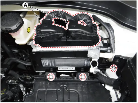
| 1. |
Remove the battery. (Refer to Engine Electrical System - "Battery") |
| 2. |
Disconnect the TCM connectors (A) and then remove the TCM after loosening the bolts and nut.
|
| Installation |
| 1. |
Install in the reverse order of removal. |
|

Description and operation Description Automatic transaxle control system relies on various measurements to determine the current control status and determine the necessary compensation values.
Specifications Specification Item Specification Type *NTC thermistor Temp.
Other information:
Kia Rio 2017-2023 YB Service Manual: Heating,Ventilation, Air Conditioning
Specifications Specification Air Conditioner Item Specification Compressor Type DVE12 Oil type & Capacity PAG 30, 120 ± 10 g Displacement 122 cc/rev Expansion valve Type
Kia Rio 2017-2023 YB Service Manual: Blower Unit
Components and components location Component Location Components 1. Intake actuator 2. Air filter 3. Air filter cover 4. Resistor 5. Mosfet 6. Intake seal 7. Intake upper cover 8.
Categories
- Manuals Home
- Kia Rio Owners Manual
- Kia Rio Service Manual
- Brake System
- Steering System
- Maintenance
- New on site
- Most important about car
