Kia Rio: Lubrication System / Oil Pan
Components and components location
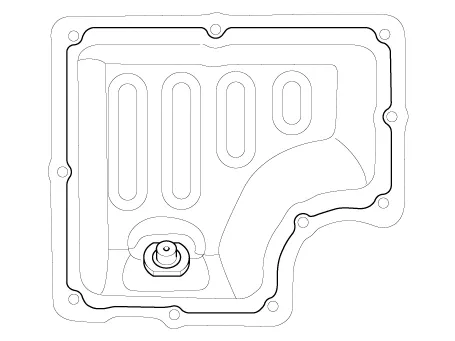
| Components |
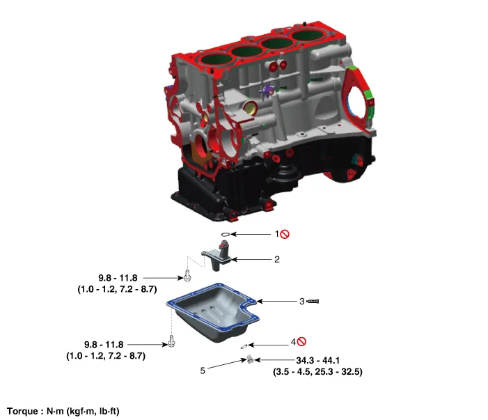
| 1. Oil screen O-ring 2. Oil screen 3. Oil pan |
4. Drain plug gasket 5. Drain plug |
Repair procedures
| Removal |
| 1. |
Remove the engine room under cover. (Refer to Engine And Transaxle Assembly - "Engine Room Under Cover") |
| 2. |
Drain engine oil. (Refer to Lubrication System - "Engine Oil") |
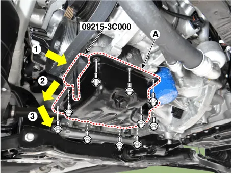
| 3. |
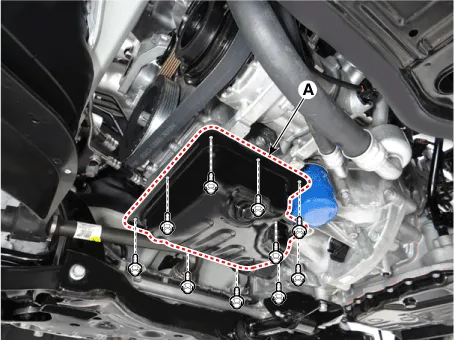
Remove the oil pan (A). Insert the blade of SST (09215-3C000) between the ladder frame and the oil pan. Cut off applied sealer and remove the oil pan.
|

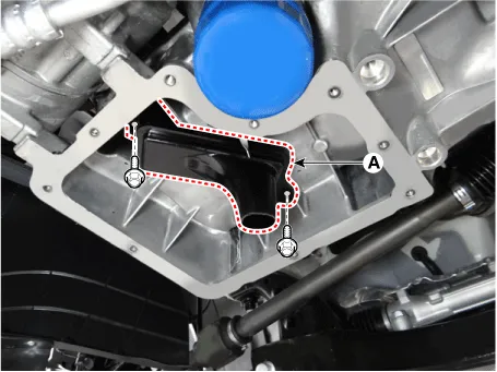
| 4. |
Remove the oil screen (A).
|
| Installation |
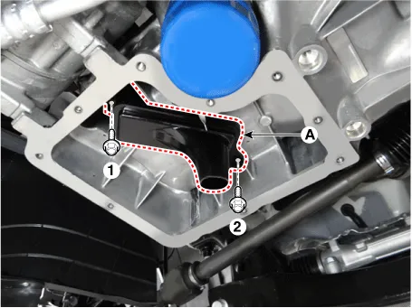
| 1. |
Install the oil screen (A), with a new O-ring. Tighten the bolts with the order blow.
|
| 2. |
Install the lower oil pan.
|
| 3. |
Install the lower oil pan (A).
Uniformly tighten the bolts in several passes.
|
| 4. |
Refill engine with engine oil. |
Repair procedures Removal and Installation 1. Disconnect the oil pressure switch connector (A) and then remove the oil pressure switch (B).
Repair procedures Removal and Installation 1. Remove the oil level gauge (A). 2. Remove the intake manifold.
Other information:
Kia Rio 2017-2023 YB Service Manual: Headlamps
Description and operation Description BI-FUNCTION 1. Definition – A headlamp with integrated functions of high and low beam – The light is controlled by rotating the shield inserted to the lens.
Kia Rio 2017-2023 YB Service Manual: Blower Motor
Repair procedures Inspection 1. Connect the battery voltage and check the blower motor rotation. 2. If the blower motor does not operate well, substitute with a known-good blower motor and check for proper operation.
Categories
- Manuals Home
- Kia Rio Owners Manual
- Kia Rio Service Manual
- Motor Driven Power Steering
- Engine Control / Fuel System
- Engine Oil and Filter
- New on site
- Most important about car
