Kia Rio: Body Electrical System / Lane Departure Warning System (LDWS)
Components and components location
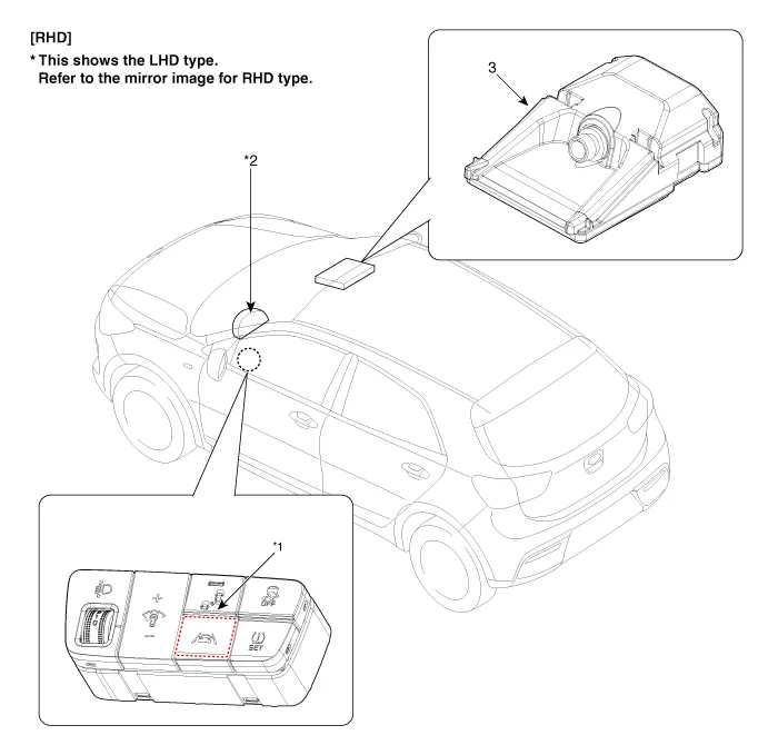
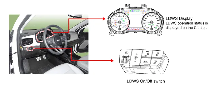
1. LDWS ON/OFF switch
2. Instrument cluster
|
3. LDWS unit (MFC)
|
※ MFC : Multi Function Camera
| – |
Function : LDWS, HBA, AEB
|
Description and operation
System block diagram
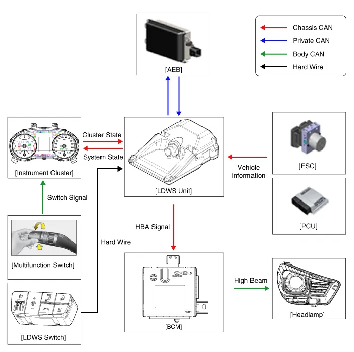
Components of LDWS
No
|
Item
|
Function
|
Position
|
1
|
LDWS Unit
|
| 1) |
Lane Departure Warning System (LDWS) : Detects the current driving
lane ahead and engages warning function if the vehicle is in danger
of departing from the current driving lane.
|
| 2) |
High Beam Assist (HBA) : Detects the headlamp light from the
oncoming vehicle and taillamp light from the vehicle ahead and turns
ON/OFF the high beam.
|
|
Windshield Glass
|
2
|
LDWS Switch
|
LDWS On/Off Switch
|
Crash Pad (Left)
|
3
|
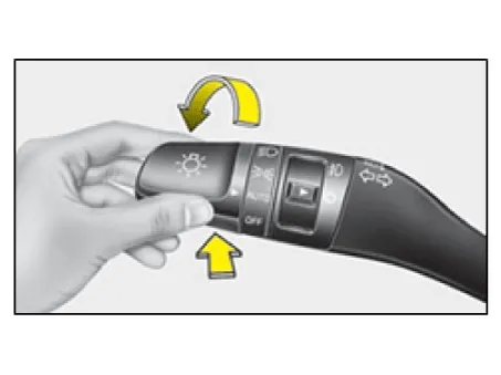
Multifunction Switch
|
HBA On/Off Switch (MF : Auto mode)
|
Steering Wheel
|
4
|
Cluster/Buzzer
|
LDWS Warning
|
Cluster
|
Camera unit of the LDWS processes the following functions using the video signal
input.
| – |
Detects and analyzes the current driving lane
|
| – |
Detects the light from foregoing vehicle and oncoming vehicle
|
| – |
Detects and analyzes the status of foregoing vehicle and oncoming vehicle,
and sets off warning sound (or message) for driver if necessary.
|
| – |
Transmits the information via high speed CAN communication
|
| 1. |
Lane Departure Warning System (LDWS) unit
Lane Departure Warning System (LDWS)
|
High Beam Assist (HBA)
|
Automatic Emergency Braking (AEB)
|
|
|

|
|
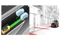
Lane Departure Warning
|
When detecting light from vehicle in front
|
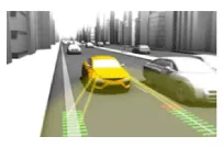
Vehicle and pedestrian detection
|
The lane departure warning system is a convenient feature that detects
the lanes ahead by using the camera image and vehicle signal data to alarm
the driver in case the vehicle deviates from the lane. It consists of the
camera unit used to detect the lane by analyzing the camera image input
signal.
The sensor module that processes screen image by sensing the lanes ahead
on the camera unit, senses the lanes and analyzes the key parameters, i.e.
vehicle center offset, road width, vehicle driving angle and road curvature,
to keep to the lane. The following procedure is the lane detecting process
through screen image processing.
| (1) |
Senses the land by inputting the road image.
|
| (2) |
Filters and calculates by magnifying the lane.
|
| (3) |
Extracts the lane candidate point.
(The constituent points are assumed as a lane.)
|
| (4) |
Senses the land by means of candidate points.
|
|
| 2. |
LDWS Operation process
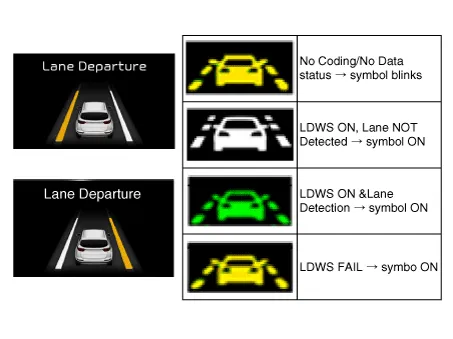
When the LDWS switch is pressed, the operation state of the lane departure
warning system is displayed at the center of the cluster as long as the
LDWS lamp is turned on.
The specific classification of the displays is shown in the following
table.
Category
|
Operation
|
LDWS Display and Alert
|
Control
(Button)
|
On
|
LDWS On
|
|
Off
|
LDWS Off
|
Operation Status
|
Cluster indicator
|
Operation Condition
|
Activates if vehicle speed exceeds set speed with LDWS ON.
[Start : 60km/h (37mph) ↑]
[Stop : 55km/h (34mph) ↓]
※ Lane departure warning is not activated if turn signal or hazard
lamp is ON.
|
|
|
|
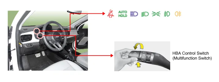
| 3. |
High Beam Assist
Category
|
Operation
|
LDWS Display and Alert
|
Control
(Button)
|
On
|
If High Beam switch is turned ON (push-return) while the Multifunction
Switch is set to Auto.
|

HBA On + Low beam
HBA On + High beam
|
Off
|
If High Beam switch is activated again while the Multifunction switch
is NOT set to Auto or when HBA is ON.
|
Operation Status
|
Cluster display
|
Operation Condition
|
Activates if vehicle speed exceeds set speed with HBA ON.
[Start: 45km/h (28mph) ↑]
[Stop: 35km/h (22mph) ↓]
※ Activates only if Multifunction switch is set to Auto and Low
Beam is ON.
|
|
|
|
LDWS ON/OFF switch
(A)
When the LDWS switch is pressed, the LDWS is activated as long as the LDWS lamp
is turned on. When the switch is pressed again, the LDWS is turned off and the display
lamp is turned off.
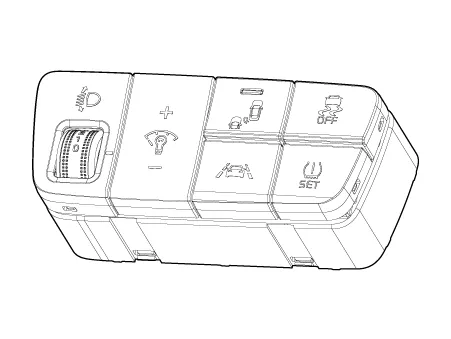
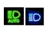
High Beam Auto Control Switch: High Beam Auto Control System is turned ON if
the Multifunction Switch Light SW is set to AUTO, and the Light SW is set to High
Beam position (Pushed).
| – |
If the Light SW is not set to AUTO, or to High Beam position, the High
Beam Auto Control System is turned OFF.
|
Alarm of LDWS
| 1. |
Visual alarm : The lane toward the direction of departure blinks in "amber".
|
Operating conditions
of LDWS
The operating conditions of LDWS are as below.
| 1. |
The LDWS switch is turned "ON". The LDWS lamp on the instrument panel
is turned on when the switch is on.
|
| 2. |
LDWS function is set and the vehicle speed exceeds 60 km/h (37 mph).
The alarm stops momentarily when the vehicle speed falls below 60 - 55
km/h (37 - 34 mph) and restarts if the vehicle speed is over 60 km/h (37
mph).
|
| 3. |
If the driver operates the left or right turn signal lamps to show the
intention of lane change, the alarm will be deactivated regardless of the
direction of lane departure.
The lane departure alarm function restarts 2 seconds after switching
off the left or right turn signal lamps. The alarm is deactivated while
operating the hazard lamps.
|
| 4. |
Switch on the turn signal lamp before changing the lanes. Arbitrary change
of lanes without operating the turn signal to the driving direction will
generate alarm.
|
| 5. |
When more than 40% of the vehicle body has crossed the lane, the alarm
is released by sensing departure for lane change.
|
| 6. |
The lane departure alarming is not made when the vehicle drives at the
center of the lane.
|
Note that LDWS may not operate properly in the following conditions.
| •
|
When the lane is not well visible due to rain, snow,
dust, puddle or other foreign materials
|
| •
|
When the sight is unclear due to bad weather such as
fog/heavy rain/heavy snow
|
| •
|
When solar beam, street lamp or light from approaching
car is reflected on the wet surface of the road
|
| •
|
When the brightness has changed abruptly after exiting
from the tunnel
|
| •
|
When the back light is illuminated strongly against the
vehicle direction
|
| •
|
When the headlamps are not used or the light beam is
too weak at night or inside the tunnel
|
| •
|
When the lane is not distinctive and the road is damaged
|
| •
|
When the shadow of median strip covers the lane
|
| •
|
When the lane and road are not distinguished due to dust
on the lane
|
| •
|
When there are more than 2 lanes to the left or right
such as bus only lanes
|
| •
|
On winding road or steep road
|
| •
|
When there are signs other than the lane on the road
surface near the lane or signs similar to the lane (e.g.
Arrow)
|
| •
|
When there is a boundary structure such as the sidewalk
block
|
| •
|
When the windshield or LDWS camera lens is contaminated
by moisture or foreign material
|
| •
|
When the distance to the foregoing car is extremely short
or the foregoing car is driving on the lane
|
| •
|
When the vehicle is severely shaking
|
| •
|
When the vehicle is passing diverging or converging lanes
or complicated crossing of lanes (e.g. Interchange and tollgate)
|
| •
|
When an object is placed on the dashboard
|
| •
|
Arrow on the road surface
|
| •
|
When the lane is too narrow or too wide
|
| •
|
When the color of the lane is hard to be distinguished
from the road
|
| •
|
When the temperature around the inside rearview mirror
is very high due to direct sunlight
|
| •
|
When the LDWS cannot sense the color of the lane due
to surrounded lighting (e.g. Inside the tunnel, the section
of sodium lamps at night or during rain)
|
| •
|
When the sight is not good enough to sense the other
lanes
|
|
| •
|
This system does not operate when the vehicle speed is
under 60km/h (37mph) or the lane marking is not sensed.
|
| •
|
Do not use windshield tinting and do not place stickers
or accessories around the inside rearview mirror.
|
| •
|
Keep the LDWS away from water.
|
| •
|
Do not disassemble or impact on the LDWS parts randomly.
|
| •
|
Do not place the reflective material (white paper or
mirror) on the dashboard as sunlight reflection may cause
malfunction.
|
| •
|
Driver may not be able to hear the LDWS alarm sound due
to excessive noise.
|
|
|
Repair procedures
| Service Point Target Auto
Calibration (SPTAC) |
This procedure provides a way to calibrate the camera by having the service technician
align the car to a well lit simulated straight road target; preferably wall mounted.
The LDWS camera will have a "System Out of Calibration" DTC set if not operating
within specified tolerances.
The LDWS will be supplied for field service replacement with the "System Calibration
Required / Variant Coding Error" DTC set if it is a replacement part delivered directly
from supplier manufacturing.
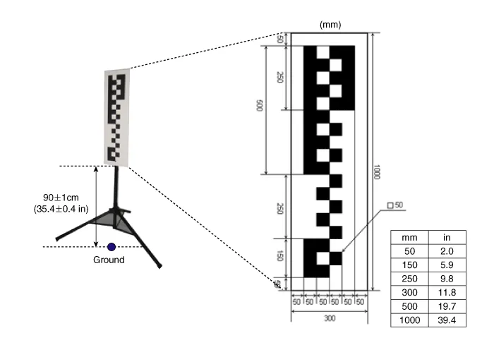
| 1. |
Guidelines for Selecting a Suitable Target
In order for LDWS Service Calibration-Static routine to complete successfully,
the following conditions are required:
| – |
Target (SST : 09890-3V100) surface must be perpendicular to the
camera in both horizontal and vertical orientation to maintain maximum
of 1° roll.
|
| – |
Target to be mounted to rigid backer material to maintain flatness
requirements.
|
| – |
Target must have reflective markings (not faded or poorly painted)
to represent lane features.
|
| – |
Target size is 30 cm wide by 100 cm high.
|
| – |
Mounting area must NOT have cross hatch patterns or textual markings
near the target.
|
| – |
Target should be well lit for optimal performance using non-fluctuating
illumination. There shall be no continuous shadow casted on the
target.
|
|
| 2. |
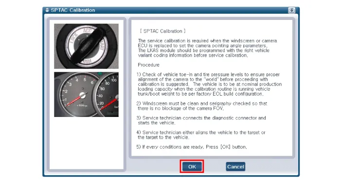
Service Point Target Auto Calibration Procedure
| (1) |
It is recommended to check vehicle toe-in and tire pressure levels
to ensure proper alignment of the camera to the "world" before proceeding
with calibration. The vehicle to run the calibration routine is
to be at nominal production loading capacity.
|
| (2) |
Windshield must be clean and silk-screen checked so that there
is no blockage of the camera.
|
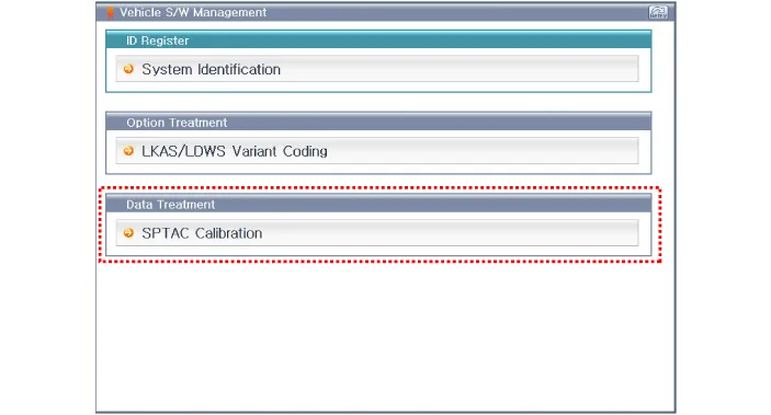
| (3) |
Service technician connects the diagnostic connector and starts
the vehicle. The camera module should not be activated by pressing
the switch.
|
| (4) |
The service calibration routine may not run correctly if any
system level fault is active.
|
| (5) |
If working with a replacement ECU: the service technician initiates
the SPTAC Reset configuration.
|
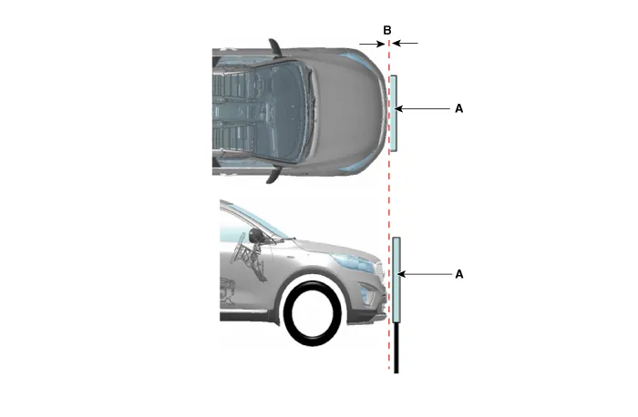
| (6) |
Service technician either aligns the vehicle to the target or
the target to the vehicle.
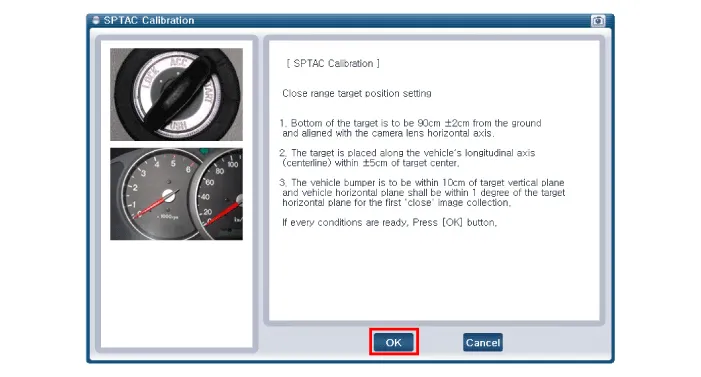
| a. |
Bottom of the target is to be 90 ±1cm (35.4 ± 0.4in)
from the ground and aligned with the camera lens horizontal
axis.
|
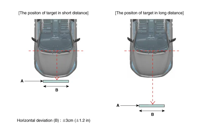
The target (A) is placed along the vehicle’s
longitudinal axis (centerline) within ±3cm (±1.2
in) of target center. (Horizontal deviation (B)
: ±3cm (±1.2 in))
|
|
| b. |
The positon of target (A) in short distance is 0 ± 5cm
(0 ± 2 in) (B) in front of front bumper.
|
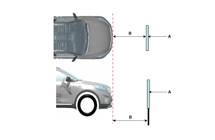
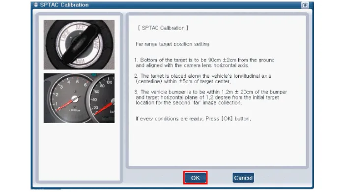
| c. |
The positon of target (A) in long distance is 100 ± 5cm
(39.4 ± 2 in) (B) in front of front bumper.
|
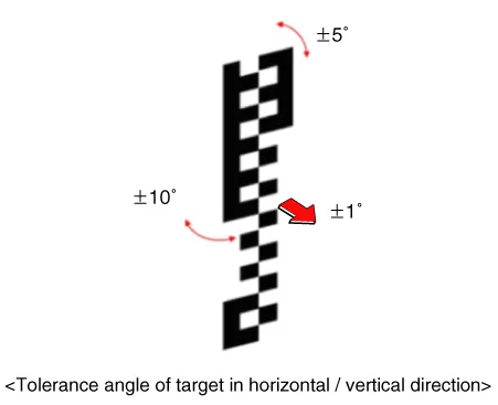
• |
The tolerance angle of target in horizontal
direction is ± 10°.
|
|
• |
The tolerance angle of target in vertical
direction is ± 5°.
|
|
• |
The tolerance angle of target in facade
center is ± 1°.
|
|
|
|
| (7) |
After confirming the calibration target location in close distance,
click "OK" on diagnostic device.
|
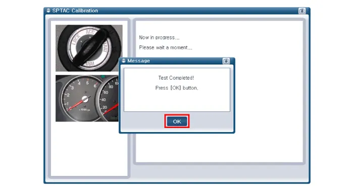
| (8) |
Technician ensures target placement location and checks the "OK"
message on the diagnostic tool (KDS/GDS).
|
| (9) |
After confirming the calibration target location in remote distance,
click "OK" on diagnostic device.
(Perform location calibration 2 times.)
|
| (10) |
Technician ensures target placement location and checks the "OK"
message on the diagnostic tool (KDS/GDS).
|
| (12) |
Turn off IGN and then on.
|
|
Test Drive
|
System may not activate properly in the following conditions:
| • |
In case lane is not visible due to glare or heavy rain.
|
| • |
In case the road is covered with snow.
|
| • |
In case puddle on the road surface reflects street light or head
light from oncoming vehicle.
|
| • |
In case there is blocking object such as sidewalk on the side
of the road.
|
| • |
In case there is trace of more than one lane due to road repair.
|
| • |
In case the distance to the foregoing vehicle is very short.
|
| • |
Be sure to perform test drive to check for normal operation after
performing optical angle test.
|
| • |
Drive on straight road (of longer than 500 m) with 2 white or
yellow lane marks at speed of over 64 km/h (40 mph), and check for
the alert as you intentionally steer close to the lane mark.
|
| • |
LDWS operates properly if the lane mark segment space is less
than 8m.
|
| • |
LDWS activates at vehicle speed above 60 km/h.
|
| • |
Perform test drive on car-only road or on a highway.
|
|
Specifications
Specification
Item
Specification
Power source
3 V
Operating temperature
-22 - 176°F (-30 - 80°C)
RF Modulation
FSK
LF Modulation
ASK
RF frequency
433.
Components and components location
Components
Repair procedures
Removal
When replacing the LDWS switch, check that the symbol mark in the cluster
operates normally by pressing the ON/OFF switch.
Other information:
Repair procedures
Removal
•
When removing with a flat-tip screwdriver or remover, wrap protective
tape around the tools to prevent damage to components.
Components and components location
Component
Driver Power Window Switch
Schematic diagrams
Circuit Diagram
[Non-Folding Mirror Type]
[Folding Mirror Type]
Repair procedures
Removal
1.


