Kia Rio: Body Electrical System / Keyless Entry And Burglar Alarm
Specifications
| Specification |
|
Item |
Specification |
|
Power source |
3 V |
|
Operating temperature |
-22 - 176°F (-30 - 80°C) |
|
RF Modulation |
FSK |
|
LF Modulation |
ASK |
|
RF frequency |
433.92 MHz |
|
Button number |
3 |
|
Function |
Door lock |
|
Door unlock |
|
|
Tailgate unlock |
Components and components location
| Component Location |
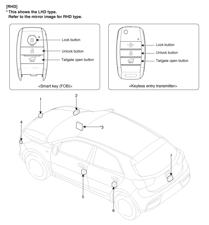
| 1. Hood switch 2. Burglar horn 3. Body control module (BCM) 4. Door lock / unlock buzzer |
5. Front door actuator & switch
6. Rear door actuator & switch 7. Tailgate actuator & switch |
Description and operation
| Description |
Burglar Alarm State [B/A State]
|
B/A State |
Description |
||||||||
|
DISARM |
|
||||||||
|
ARMWAIT |
|
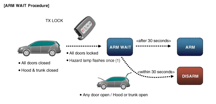
※ Remark: For a vehicle equipped with Smart Key system, the same process is applied to Passive door lock function.
|
B/A State |
Description |
||||||||||||
|
AUTO LOCK TIMER 1 |
|
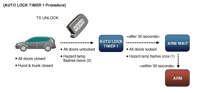
※ Remark: For a vehicle equipped with Smart Key system, the same process is applied to Passive door lock function.
|
B/A State |
Description |
||||||||||
|
AUTO LOCK TIMER 2 |
|
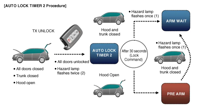
※ Remark: For a vehicle equipped with Smart Key system, the same process is applied to Passive door lock function.
|
B/A State |
Description |
|
PRE ARM |
1-1. This is the state right before entering "ARM" mode after AUTO LOCK
Timer 2 is completed and all doors are closed. 1-2. If the driver closes hood or tailgate, hazard lamp blinks one time and then the vehicle automatically enters "ARM" mode via "ARM WAIT" mode. 2-1. If LOCK button is pressed while at least one of all doors, hood and tailgate is open, "PRE ARM" mode turns on. 2-2. Because all doors locking signal is issued but the conditions for "ARM WAIT" are not satisfied, the vehicle remains in standby mode and enters ARM mode via ARM WAIT mode as soon as the door being open is closed. 2-3. In case intrusion is detected in PRE ARM mode, the vehicle turns into DISARM mode. 2-4. Security indicator keeps blinking in PRE ARM mode. |

|
B/A State |
Description |
||||||
|
RE ARM |
|
|
B/A State |
Description |
||||||||||
|
AUTOLOCK TIMER3 |
|
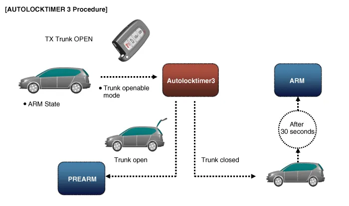
|
B/A State |
Description |
||||||||||||||
|
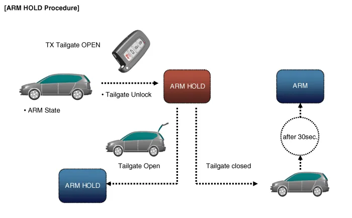
ARM HOLD (Alarm hold : Tailgate) ※Non-PTL option |
|
Note 1: ARM HOLD is a mode that defers activation of ARM mode only for tailgate. During ARM HOLD mode, ARM mode is applied to doors and hood.
Note 2: When using the ignition key to open the tailgate, the ARM HOLD function works in the same way, provided that the "Door Key Burglar Alarm" function should be enabled. if this is disabled, the key-based ARM HOLD is off and using the key to opening the tailgate is determined as a theft and the alarm is issued.
|
B/A State |
Description |
||||||
|
RE ARM (ARM mode is on again) |
|
||||||
|
RESET |
|
|
B/A State |
Description |
||||
|
KEY ON 30 second deactivation (Non-Smart Key option) |
|
||||
|
When ARM mode is on, the tailgate OPEN and central door unlock are not allowed.
|
|
Repair procedures
| Inspection |
|

Front Door Lock Module Inspection
| 1. |
Remove the front door trim. (Refer to Body - "Front Door Trim") |
| 2. |
Remove the front door trim seal. (Refer to Body - "Front Door Window Glass") |
| 3. |
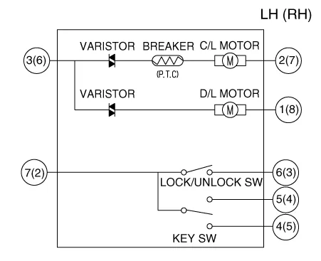
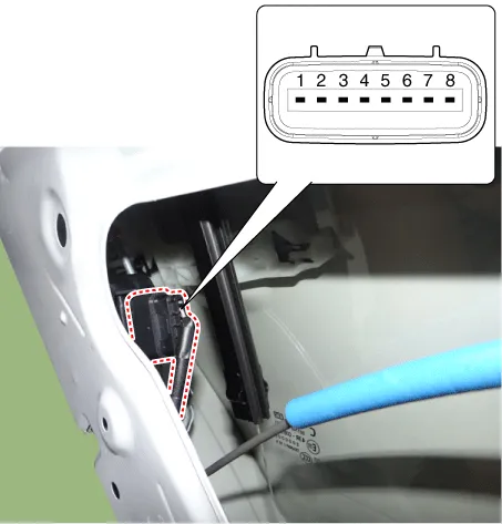
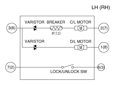
Disconnect the connector from the actuator.
[Central Lock Motor]
[Dead Lock Motor]
|
||||||||||||||||||||||||||||||||||||||||||||||||||||||||||
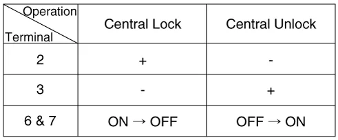
| 4. |
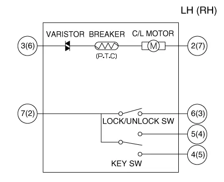
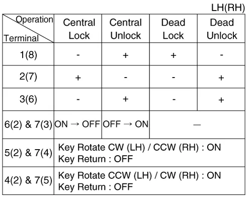
Check actuator operation by connecting power and ground as shown below. To prevent damage to the actuator, apply battery voltage only momentarily. [Central Lock Motor]
[Dead Lock Motor]
[Central Lock Motor] (LH)
(RH)
[Dead Lock Motor]
|


Rear Door Lock Module Inspection
| 1. |
Remove the rear door trim. (Refer to Body - "Rear Door Trim") |
| 2. |
Remove the rear door trim seal. (Refer to Body - "Rear Door Window Glass") |
| 3. |
Disconnect the connector from the actuator.
[Central Lock Motor]
[Dead Lock Motor]
|
||||||||||||||||||||||||||||||||||||||||||||||||||||||||||
| 4. |
Check actuator operation by connecting power and ground as shown below. To prevent damage to the actuator, apply battery voltage only momentarily. [Central Lock Motor]
[Dead Lock Motor]
[Central Lock Motor] (LH)
(RH)
[Dead Lock Motor]
|


Tailgate Lock Module Inspection
| 1. |
Remove the tailgate trim. (Refer to Body - "Tailgate Trim") |
| 2. |
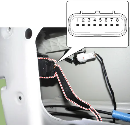
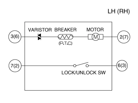
Disconnect the connectors from the actuator.
|
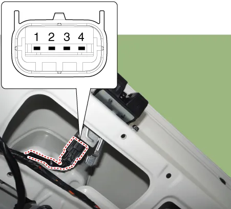
| 3. |
Check actuator operation by connecting power and ground as shown below. To prevent damage to the actuator, apply battery voltage only momentarily.
|
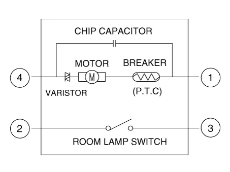

| 4. |
Checking the tailgate of the vehicle power option power refers to the tailgate module. |
Tailgate Open Switch Inspection
| 1. |
Disconnect the negative (-) battery terminals. |
| 2. |
Remove the tailgate trim (Refer to Body - "Tailgate Trim") |
| 3. |
Disconnect the tailgate open switch assembly connector.
|
| 4. |
Check for continuity between terminals in half latching condition as shown below.
|

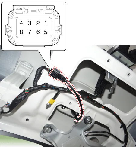
Hood Switch Inspection
| 1. |
Disconnect the hood switch connector (A).
|

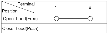
| 2. |
Check for continuity between the terminals and ground as shown below. (Refer to Body - "Hood Latch Assembly")
|
Burglar Horn Inspection
| 1. |
Remove the burglar horn (A) after loosening the mounting bolt and disconnecting the connector (B).
|

| 2. |
Test the burglar horn by connecting battery power to the terminal 2 and ground the terminal 1.
|

Components and components location Components [Standard Type ("3.5")] [Supervision Type ("3.5")] Connector Pin Information Connector A No.
Components and components location Components 1. LDWS ON/OFF switch 2. Instrument cluster 3. LDWS unit (MFC) ※ MFC : Multi Function Camera – Function : LDWS, HBA, AEB Description and operation Description System block diagram Components of LDWS No Item Function Position 1 LDWS Unit 1) Lane Departure Warning System (LDWS) : Detects the current driving lane ahead and engages warning function if the vehicle is in danger of departing from the current driving lane.
Other information:
Kia Rio 2017-2023 YB Service Manual: Power Door Locks
Components and components location Component Location 1. Driver power window switch 2. Assist power window switch 3 . Body Comtrol Module (BCM) 4 . Tailgate actuator 5 . Door latch lock actuator 6 .
Kia Rio 2017-2023 YB Service Manual: Power Mosfet (FATC)
Repair procedures Inspection 1. Turn the ignition switch ON. 2. Manually operate the control switch and measure the voltage of blower motor. 3. Select the control switch to raise voltage until high speed.
Categories
- Manuals Home
- Kia Rio Owners Manual
- Kia Rio Service Manual
- Body (Interior and Exterior)
- Body Electrical System
- Heating,Ventilation, Air Conditioning
- New on site
- Most important about car
