Kia Rio: Audio / Multimedia Jack
Schematic diagrams
| Circuit Diagram |
Description and operation
| Description |
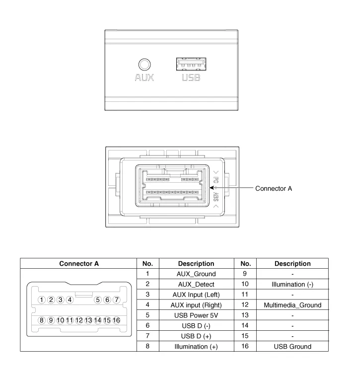
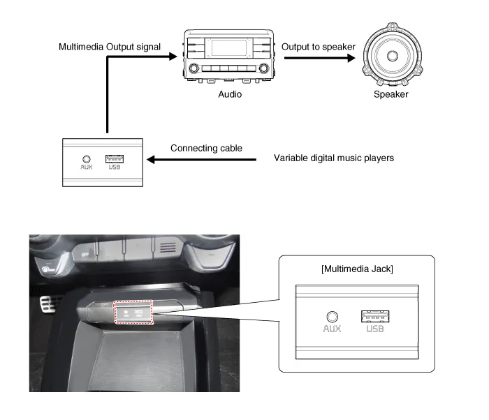
The multimedia jack on the console upper cover is for customers who like to listen to external portable music players like the MP3 etc., through the vehicle's sound system when it is linked to this jack. The customer has this added option.
In case of distorted sound coming from the AUX-linked external music players, the audio unit may not be defective but the output level of the player does not match the specification of the AUX.
Repair procedures
| Removal |
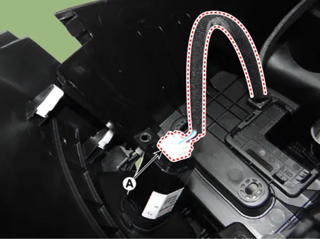
Multimedia Jack
Put on gloves to protect your hands. |

|

| 1. |
Disconnect the negative (-) battery terminal. |
| 2. |
Remove the front console upper cover. (Refer to Body - "Floor Console Assembly") |
| 3. |
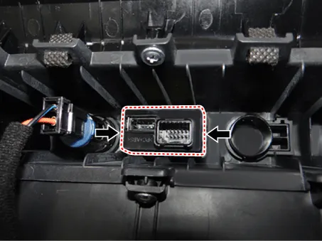
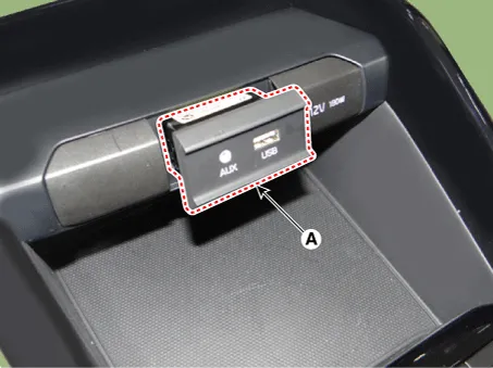
Remove the multimedia jack (A) after releasing the fixed hooks.
|
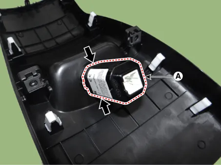
USB Charger
Put on gloves to protect your hands. |
|
| 1. |
Disconnect the negative (-) battery terminal. |
| 2. |
Remove the floor console assembly. (Refer to Body - "Floor Console Assembly") |
| 3. |
Disconnect the USB charger connector (A).
|
| 4. |
Remove the USB charger (A) after releasing the fixed hooks.
|
| Installation |
Multimedia Jack
| 1. |
Install the multimedia jack. |
| 2. |
Install the front console upper cover. |
| 3. |
Connect the negative (-) battery terminal.
|
USB Charger
| 1. |
Install the USB charger. |
| 2. |
Connect the USB charger connector. |
| 3. |
Install the floor console assembly. |
| 4. |
Connect the negative (-) battery terminal.
|
Components and components location Components 1. Left Remote Control Switch (Audio + Hands free + Voice) 2. Right Remote Control Switch (Cruise+Trip Computer) Schematic diagrams Circuit Diagram [Audio] [Audio + Bluetooth] [Audio + Bluetooth + Voice] [Trip] [Trip + ACC (2 Button)] [Trip + ACC + SLD (2 Button)] [Trip + ACC (4 Button)] [Trip + ACC + SLD (4 Button)] Repair procedures Removal 1.
Specifications Specifications Items Specifications Rated voltage 5V Load Max.
Other information:
Kia Rio 2017-2023 YB Service Manual: Auto Defogging Sensor (FATC only)
Description and operation Description The Auto Defogging Sensor is installed on front windshild glass. The Auto Defogging Sensor senses moisture on the windshild. The air conditioner control module receives the signal from the sensor and eliminate the fog by controlling the intake actuator, A/C, auto defogging actuator, blower m
Kia Rio 2017-2023 YB Service Manual: PTC Heater
Description and operation Description The PTC (Positive Temperature Coefficient) heater is installed at the exit or the backside of heater core. The PTC heater is an electric heater using a PTC element as an auxiliary heating device that supplements deficiency of interior heat source in highly effective diesel engine.
Categories
- Manuals Home
- Kia Rio Owners Manual
- Kia Rio Service Manual
- Engine Electrical System
- Steering System
- Motor Driven Power Steering
- New on site
- Most important about car
