Kia Rio: Fuses And Relays / Junction Box (Passenger Compartment)
Components and components location
| Component Location |
| I/P Junction Block |
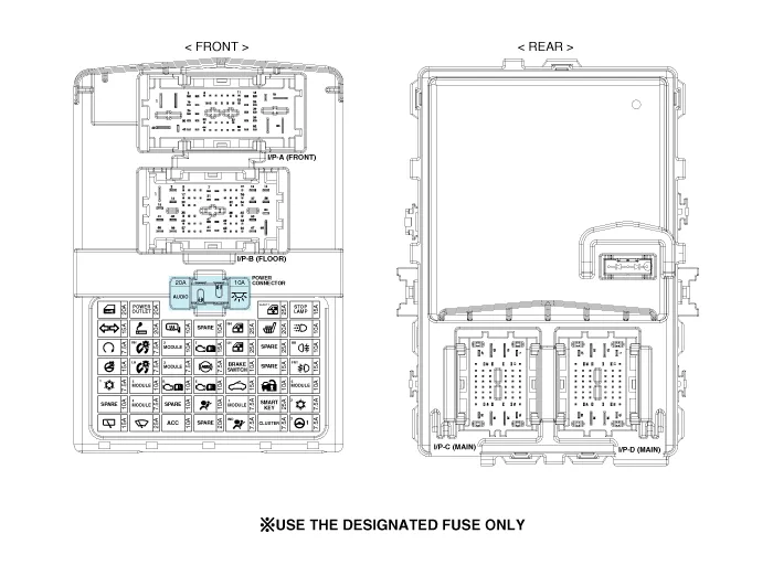
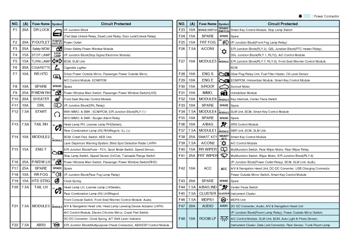
| Circuit (I/P Junction Block) |
Repair procedures
| Fuse Inspection |
| 1. |
Check that the fuse holders are loosely held and that the fuses are securely fixed by the holders. |
| 2. |
Check that each fuse circuit has the exact fuse capacity. |
| 3. |
Check the fuses for any damage.
|

| Diagnosis with KDS/GDS |
| 1. |
The Interior Junction Block can be diagnosed by using the KDS/GDS. The Interior Junction Block communicates with the KDS/GDS which then displays inputs and outputs along with codes. |
| 2. |
To diagnose the Interior Junction Block function, select the vehicle model, Interior. |
| 3. |
To consult the present input/out value of Interior Junction Block, "Current DATA". It provides information of Interior Junction Block input/output conditions.
|
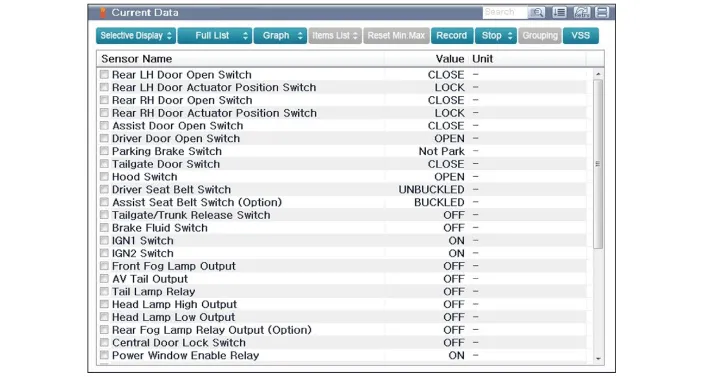
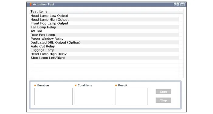
| 4. |
To perform functional test on Interior Junction Block outputs, select "Actuation Test"
|
| Removal |
| 1. |
Disconnect the negative (-) battery terminal. |
| 2. |
Remove the crash pad lower panel. (Refer to Body - "Crash Pad Lower Panel") |
| 3. |
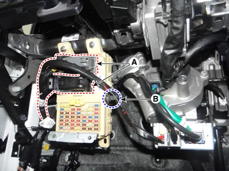
Disconnect the connectors (A) from the fuse side of the interior junction block. |
| 4. |
Remove the interior junction block wiring mounting clip (B).
|
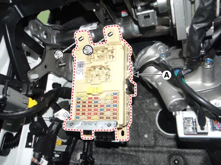
| 5. |
Remove the interior junction block (A) after loosening the mounting nuts.
|
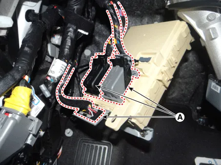
| 6. |
Disconnect the connectors (A) from the back of the interior junction block.
|
| Installation |
| 1. |
Install the interior junction block. |
| 2. |
Connect the interior junction block connectors. |
| 3. |
Install the crash pad lower panel. |
| 4. |
Connect the negative (-) battery terminal. |
| 5. |
Check that all systems operate properly. |
Components and components location Component Location E/R Junction Block Circuit (PCB Block) E/R Junction Block Circuit (PCB Block) E/R Junction Block Circuit (PCB Block) E/R Junction Block Circuit (PCB Block) Gasoline / Diesel Junction Block Repair procedures Inspection 1.
Components and components location Component Location 1. Headlamp assembly (Built in leveling actuator) 2. Headlamp leveling switch
Other information:
Kia Rio 2017-2023 YB Service Manual: Photo Sensor (FATC only)
Description and operation Description The photo sensor is located at the center of defrost nozzles. The photo sensor contains a photovoltaic (sensitive to sunlight) diode. The solar radiation received by its light receiving portion, generates an electromotive force in proportion to the amount of radiation received which is tran
Kia Rio 2017-2023 YB Service Manual: Climate Control Air Filtar
Description and operation Description The climate control air filter is located in the bower unit. It eliminates foreign materials and odor. The particle filter performs a role as an odor filter as well as a conventional dust filter to ensure comfortable interior environment.
Categories
- Manuals Home
- Kia Rio Owners Manual
- Kia Rio Service Manual
- Engine Electrical System
- Heating,Ventilation, Air Conditioning
- Timing Chain
- New on site
- Most important about car
