Kia Rio: Fuses And Relays / Junction Box (Engine Compartment)
Components and components location
| Component Location |
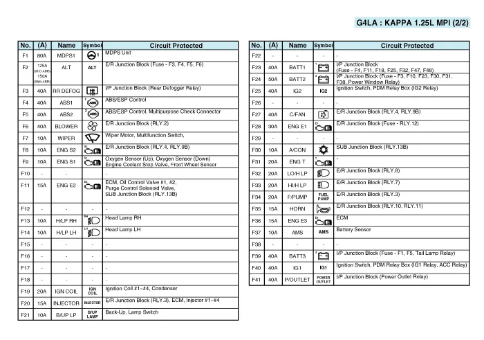
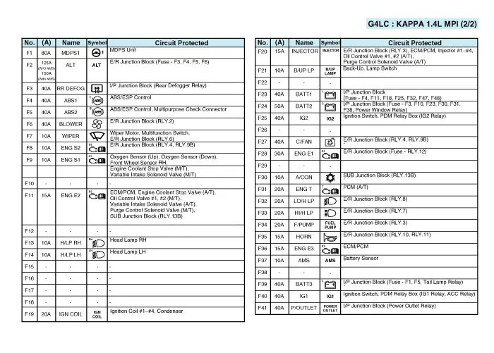
| E/R Junction Block |
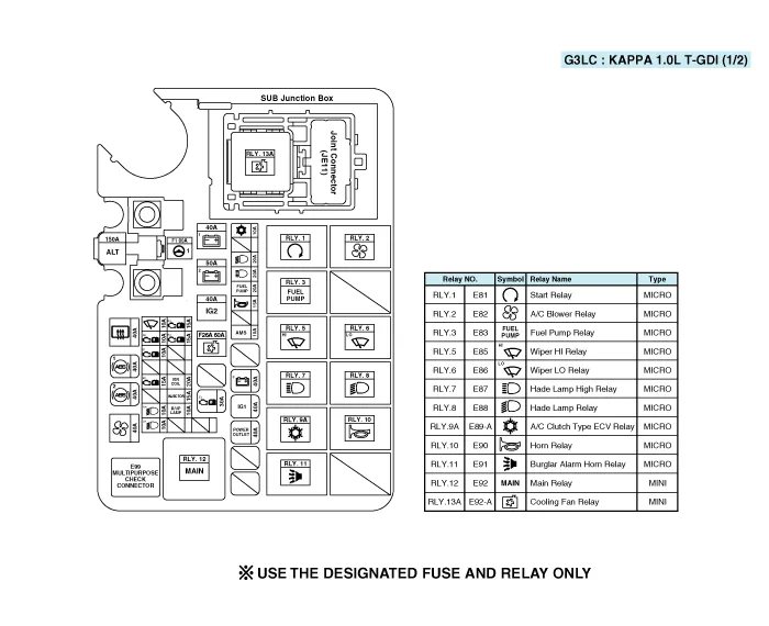
| Circuit (PCB Block) |
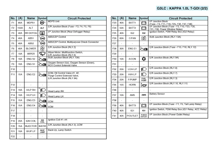
| E/R Junction Block |
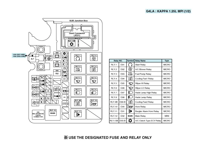
| Circuit (PCB Block) |
| E/R Junction Block |

| Circuit (PCB Block) |
| E/R Junction Block |
| Circuit (PCB Block) |
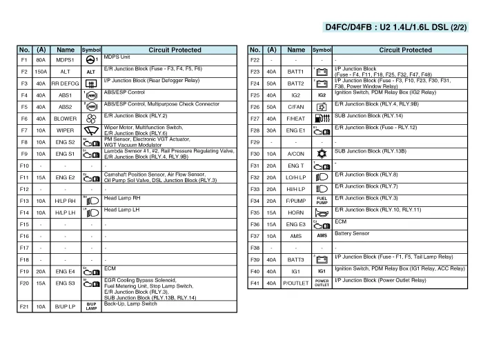
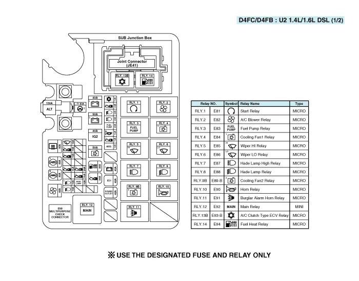
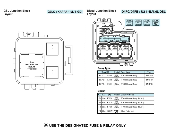
| Gasoline / Diesel Junction Block |
Repair procedures
| Inspection |
| 1. |
Disconnect the negative (-) battery terminal. |
| 2. |
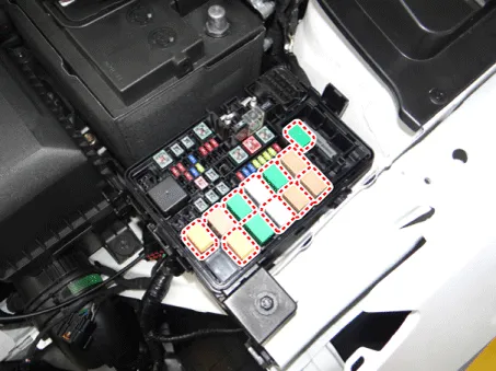
Pull out the relay from the engine compartment relay block. |
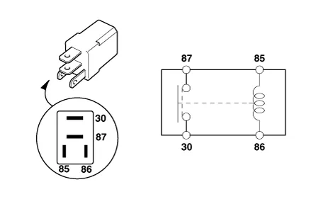
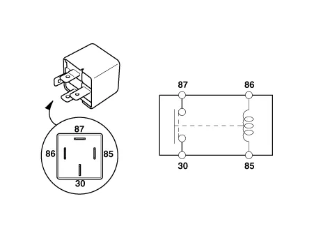
Power Relay (Type A)
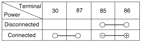
Check for continuity between the terminals.
| 1. |
After supplying power to between No. 85 and 86 power relay terminals, check that there is continuity between No. 30 and 87 terminals. |
| 2. |
After disconnecting power between No. 85 and 86 power relay terminals, check that there is no continuity between No. 30 and 87 terminals. Engine Room Relay Block
|
Power Relay (Type B)
Check for continuity between the terminals.
| 1. |
After supplying power to between No. 85 and 86 power relay terminals, check that there is continuity between No. 30 and 87 terminals. |
| 2. |
After disconnecting power between No. 85 and 86 power relay terminals, check that there is no continuity between No. 30 and 87 terminals.
|

Fuse
| 1. |
Check that the fuse holders are loosely held and that the fuses are securely fixed by the holders. |
| 2. |
Check that each fuse circuit has the exact fuse capacity. |
| 3. |
Check the fuses for any damage.
|

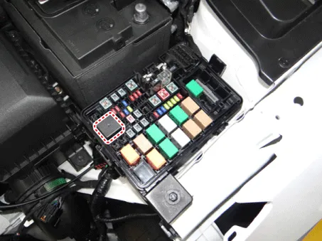
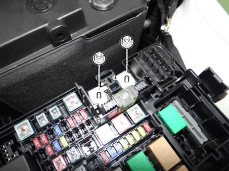
Multi Fuse
| 1. |
Disconnect the negative (-) battery terminal. |
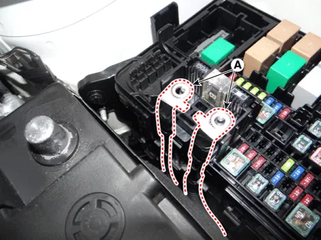
| 2. |
Remove the power cable terminals (A) after loosening the nuts from the engine room fuse & relay box.
|
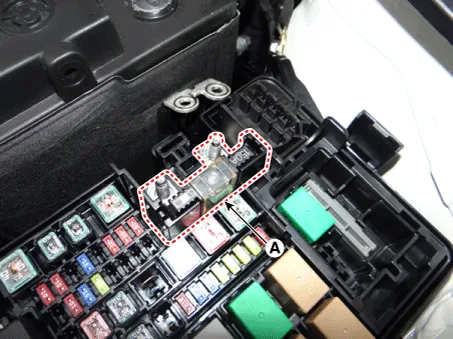
| 3. |
Remove the multi fuse (A) after pushing the hook.
|
|

Components and components location Component Location [Engine Room] 1. Engine room relay block [Interior Relay] 1.
Components and components location Component Location I/P Junction Block Circuit (I/P Junction Block) Repair procedures Fuse Inspection 1.
Other information:
Kia Rio 2017-2023 YB Service Manual: Smart Key Unit
Components and components location Components Connector Pin Information No. Connector A Connector B Connector C 1 - IGN2 Relay_output Battery (+)_Signal 2 SSB Switch1 signal_input P-CAN
Kia Rio 2017-2023 YB Service Manual: Temperature Control Actuator
Description and operation Description The heater unit includes mode control actuator and temperature control actuator. The temperature control actuator is located at the heater unit. It regulates the temperature by the procedure as follows.
Categories
- Manuals Home
- Kia Rio Owners Manual
- Kia Rio Service Manual
- Clutch System
- Maintenance
- Engine Mechanical System
- New on site
- Most important about car
