Kia Rio: Front Suspension System / Front Stabilizer Bar
Repair procedures
| Removal |
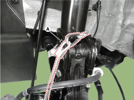
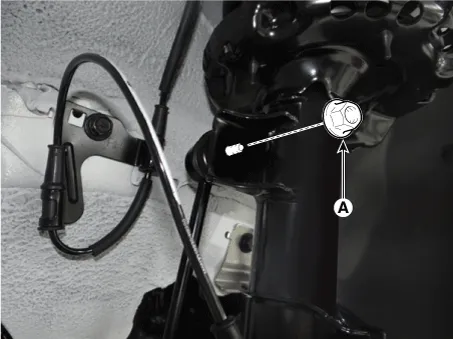
| 1. |
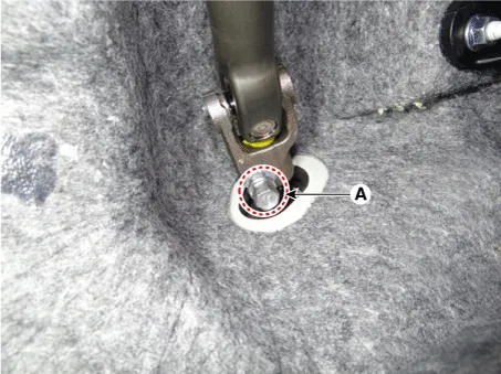
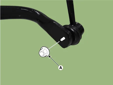
Remove the universal joint bolt (A).
|

| 2. |
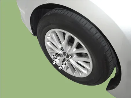
Remove wheel nuts, front wheel and tire from front hub.
|
| 3. |
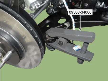
Remove the tie rod end ball joint from the knuckle by using the SST (09568-34000).
|
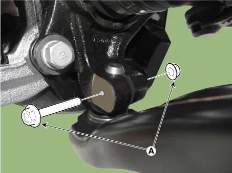
| 4. |
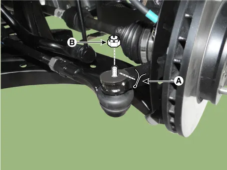
Remove the lower arm bolt and nut (A).
|
| 5. |
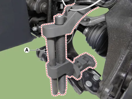
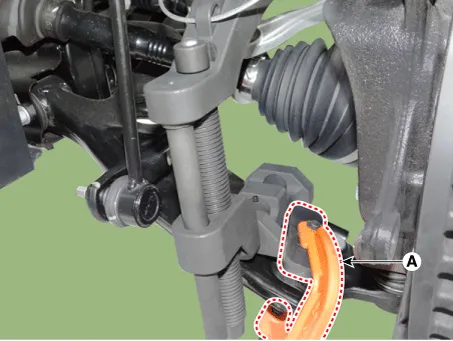
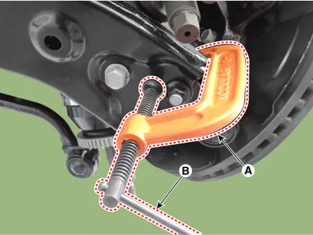
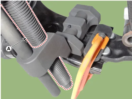
Remove the front lower arm from the front knuckle using the SST (0K545-A9100).
|
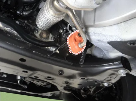
| 6. |
Remove the stabilizer link nut (A).
|

| 7. |
Remove the hanger.
|
| 8. |
Remove the roll rod bracket. D 1.4 U2 TCI (Refer to Engine Mechanical System - "Engine Mounting") G 1.0 T-GDI (Refer to Engine Mechanical System - "Engine Mounting") G 1.2 MPI (Refer to Engine Mechanical System - "Engine Mounting") G 1.4 MPI (Refer to Engine Mechanical System - "Engine Mounting") |
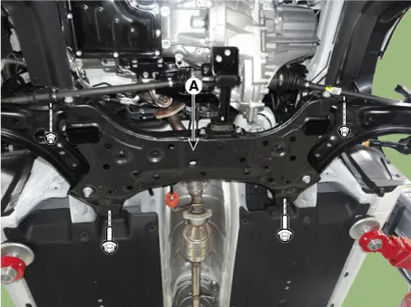
| 9. |
Loosen the bolts & nuts and then remove the sub frame (A).
|
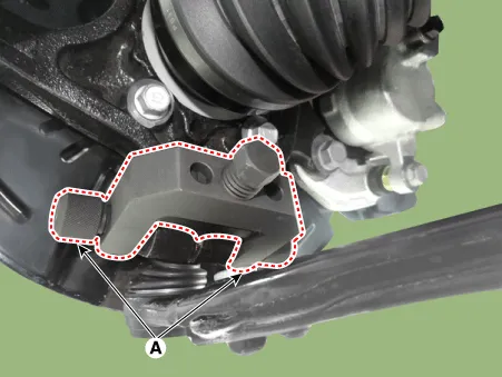
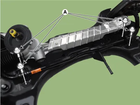
| 10. |
Loosen the bolts (A) and then remove the stabilizer bar assembly.
|
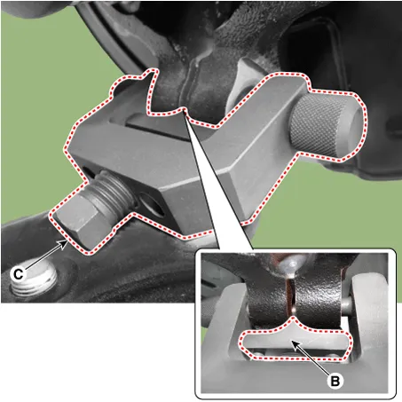
| 11. |
Loosen the nut (A) and then remove the stabilizer link.
|
| 12. |
Install in the reverse order of removal. |
| 13. |
Check the wheel alignment. (Refer to Tires/Wheels - "Alignment") |
| Inspection |
| 1. |
Check the bushing for wear and deterioration. |
| 2. |
Check the front stabilizer bar for deformation. |
| 3. |
Check the front stabilizer link ball joint for damage. |
Repair procedures Removal 1. Remove wheel nuts, front wheel and tire from front hub. Tightening torque: 107.
Repair procedures Removal 1. Remove the universal joint bolt (A). Tightening torque : 32.4 - 37.3 N·m (3.
Other information:
Kia Rio 2017-2023 YB Service Manual: License Lamps
Repair procedures Removal 1. Disconnect the negative (-) battery terminal. 2. Remove the license lamp assembly (A) after pressing the locking pin. 3. Disconnect the license lamp connector (A).
Kia Rio 2017-2023 YB Service Manual: Smart Key System
Specifications Specifications Smart Key Unit Items Specification Rated voltage DC 12 V Operating voltage DC 9 - 16 V Operating temperature -31 - 167°F (-35 - 75°C) Load Max.
Categories
- Manuals Home
- Kia Rio Owners Manual
- Kia Rio Service Manual
- Emission Control System
- Coolant
- Steering System
- New on site
- Most important about car
