Kia Rio: Front Suspension System / Front Lower Arm
Repair procedures
| Removal |
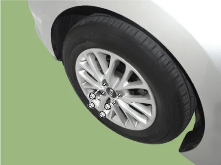
| 1. |
Remove wheel nuts, front wheel and tire from front hub.
|

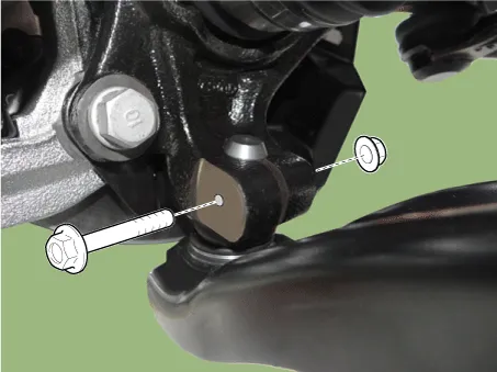
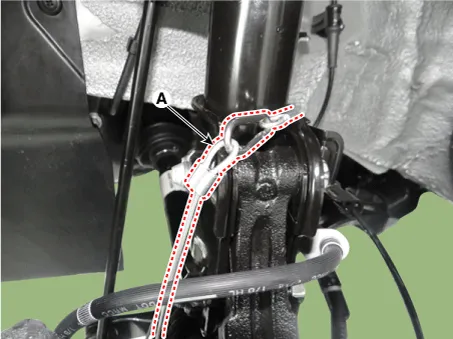
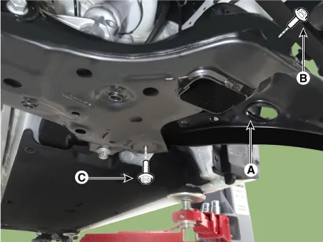
| 2. |
Remove the lower arm bolt and nut (A).
|
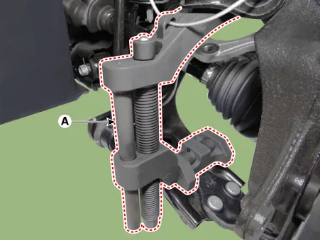
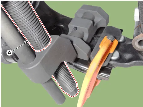
| 3. |
Remove the front lower arm from the front knuckle using the SST (0K545-A9100).
|
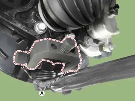
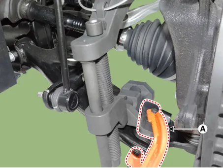
| 4. |
Remove the lower arm (A) from the sub frame.
|
| 5. |
Install in the reverse order of removal. |
| 6. |
Check the wheel alignment. (Refer to Tires/Wheels - "Alignment") |
Lower arm ball joint
| 1. |
Remove the front lower arm. (Refer to Suspension System - "Front Lower Arm") |
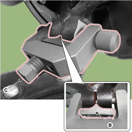
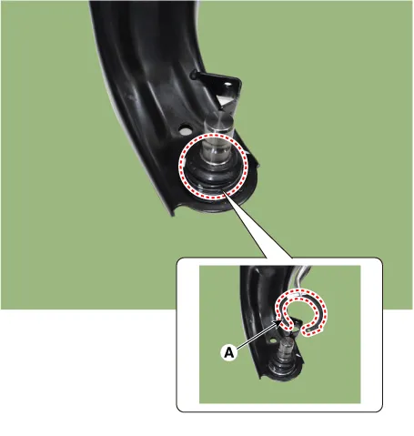
| 2. |
Remove the snap ring (A) from the lower arm ball joint.
|
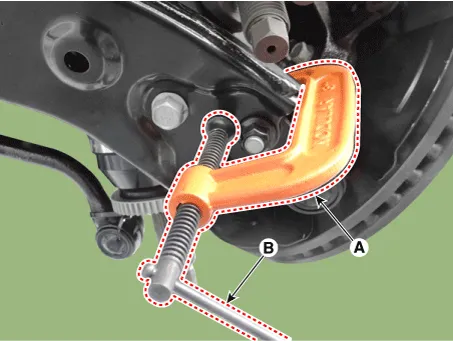
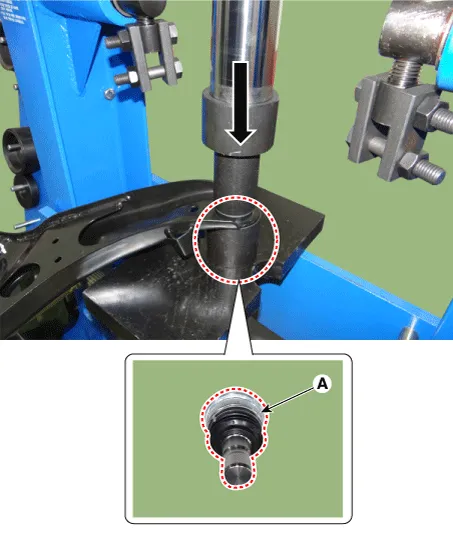
| 3. |
Using a press, remove the ball joint (A) from the lower arm.
|
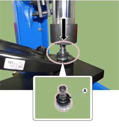
| 4. |
Using a press, install the new ball joint.
|
| Inspection |
| 1. |
Check the bushing for wear and deterioration. |
| 2. |
Check the lower arm for bending or breakage. |
| 3. |
Check the lower arm for deformation. |
| 4. |
Check all bolts and nuts. |
Components and components location Components Location 1. Lock nut 2. Insulator dust cap 3. Self lock nut 4. Strut insulator 5.
Repair procedures Removal 1. Remove the universal joint bolt (A). Tightening torque : 32.4 - 37.3 N·m (3.
Other information:
Kia Rio 2017-2023 YB Service Manual: Room Lamp
Repair procedures Removal • Put on gloves to prevent hand injuries. • When removing with a flat-tip screwdriver or remover, wrap protective tape around the tools to prevent damage to componen
Kia Rio 2017-2023 YB Service Manual: A/C Pressure Transducer
Description and operation Description The A/C Pressure Transducer (APT) convert the pressure value of high pressure line into voltage value after measure it. By converted voltage value, engine ECU controls cooling fan by operating it high speed or low speed.
Categories
- Manuals Home
- Kia Rio Owners Manual
- Kia Rio Service Manual
- Body (Interior and Exterior)
- Maintenance
- Coolant
- New on site
- Most important about car
