Kia Rio: Brake System / Brake Pedal
Components and components location
| Components |
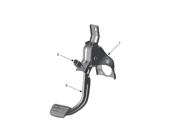
| 1. Brake member assembly 2. Stop lamp switch |
3. Pedal assembly |
Repair procedures
| Removal |
| 1. |
Switch "OFF" ignition and disconnect the negative (-) battery terminal. |
| 2. |
Remove the crash pad lower panel. (Refer to Body - "Crash Pad Lower Panel") |
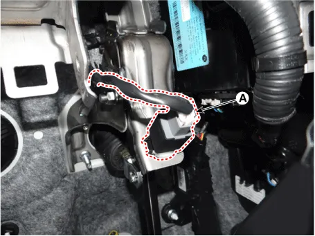
| 3. |
Disconnect the brake switch connector (A).
|
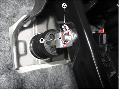
| 4. |
Disconnect the snap pin (A) and clevis pin (B).
|
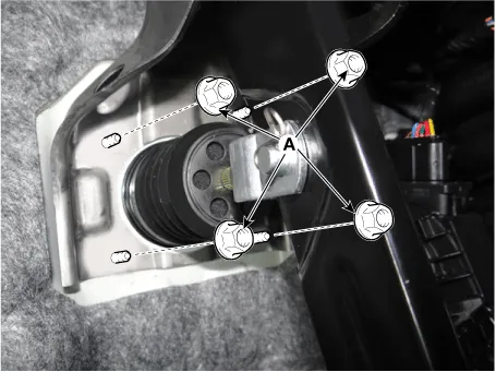
| 5. |
Remove the brake pedal mounting nuts (A).
|
| Inspection |
| 1. |
Check the bushing for wear. |
| 2. |
Check the brake pedal for bending or twisting. |
| 3. |
Check the brake pedal return spring for damage. |
| Installation |
| 1. |
Install in the reverse order of removal |
Components and components location Components Repair procedures Removal 1. Disconnect the brake fluid level switch connector (A) and then remove the reservoir cap.
Components and components location Components 1. Caliper body 2. Caliper carrier 3. Brake pad assembly [IN] 4.
Other information:
Kia Rio 2017-2023 YB Service Manual: Indicators And Gauges
Troubleshooting Troubleshooting Error Item Failure symptom Inspection items Detailed inspections Relevant Parts/ Components Screen display LCD screen does not turn on 1) Connector attachments
Kia Rio 2017-2023 YB Service Manual: Compressor Oil
Repair procedures Oil Specification 1. The HFC-134a system requires synthetic compressor oil (PAG) whereas the R-12 system requires mineral compressor oil. The two oils must never be mixed. 2. Compressor oil (PAG) varies according to compressor model.
Categories
- Manuals Home
- Kia Rio Owners Manual
- Kia Rio Service Manual
- Clutch System
- Emission Control System
- Engine Oil and Filter
- New on site
- Most important about car
