Kia Rio: Brake System / Front Disc Brake
Components and components location
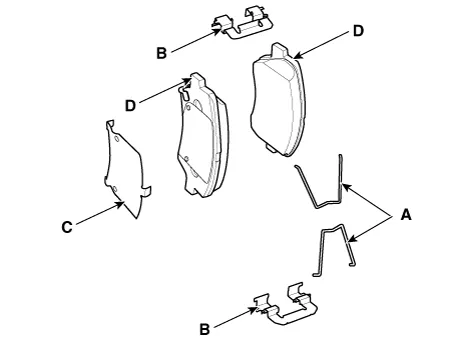
| Components |
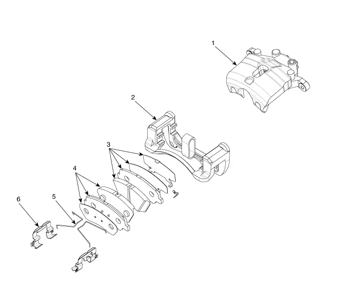
| 1. Caliper body 2. Caliper carrier 3. Brake pad assembly [IN] |
4. Brake pad assembly [OUT]
5. Pad return spring 6. Pad liner |
Repair procedures
| Removal |
Brake Pad
| 1. |
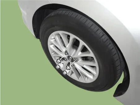
Remove the front wheel & tire.
|
| 2. |
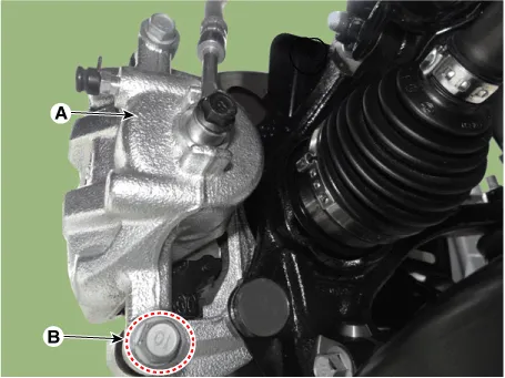
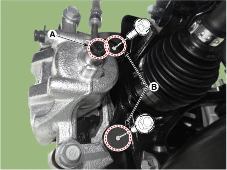
Loosen the guide rod bolt (B) and then pivot the caliper body (A) up out of the way.
|
| 3. |
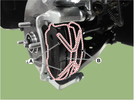
Remove the pad return spring (A) and then separate the brake pad (B).
|

Caliper Assembly
| 1. |
Remove the front wheel & tire.
|
| 2. |
Loosen the guide rod bolt (B) and then pivot the caliper body (A) up out of the way.
|
| 3. |
Remove the pad return spring (A) and then separate the brake pad (B).
|
| 4. |
Loosen the bolts (A,B) and then remove the brake caliper.
|
Disc
| 1. |
Remove the front wheel & tire.
|
| 2. |
Loosen the guide rod bolt (B) and then pivot the caliper body (A) up out of the way.
|
| 3. |
Remove the pad return spring (A) and then separate the brake pad (B).
|
| 4. |
Loosen the bolts (A,B) and then remove the brake caliper.
|
| 5. |
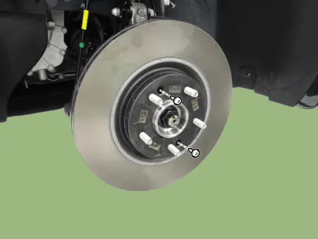
Remove the brake disc after loosening the screw.
|
| Inspection |
Front brake disc thickness check
| 1. |
Check the brake pads for wear and fade. |
| 2. |
Check the brake disc for damage and cracks. |
| 3. |
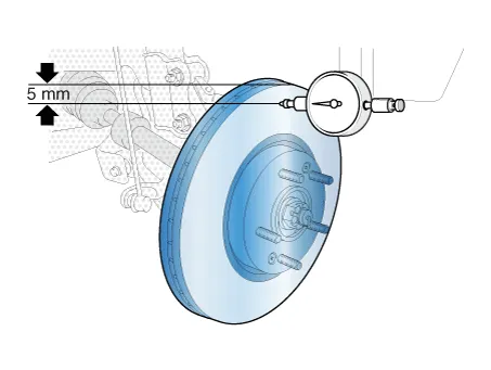
Remove all rust and contamination from the surface, and measure the disc thickness at 8 points, at least, at the same distance (5mm) apart from the brake disc outer circle.
|
| 4. |
If wear exceeds the limit, replace the discs and pad assembly left and right of the vehicle. |
Front Brake Pad Check
| 1. |
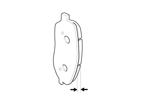
Check the pad wear. Measure the pad thickness and replace it, if it is less than the specified value.
|
| 2. |
Check that grease is applied to sliding contact points and check the pad and backing metal for damage.
|
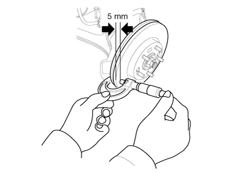
Front brake disc runout check
| 1. |
Place a dial gauge about 5mm (0.2 in.) from the outer circumference of the brake disc, and measure the runout of the disc.
|
| 2. |
If the runout of the brake disc exceeds the limit specification, replace the disc, and then measure the runout again. |
| 3. |
If the runout does not exceed the limit specification, install the brake disc after turning it 180° and then check the brake disc again for runout. |
| 4. |
If the runout cannot be corrected by changing the position of the brake disc, replace the brake disc. |
| Installation |
| 1. |
Install in the reverse order of removal. |
| 2. |
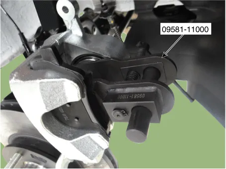
Use the SST (09581-11000) when installing the brake caliper assembly.
|
| 3. |
After installation, bleed the brake system. (Refer to Brake system - "Brake System") |
Components and components location Components 1. Brake member assembly 2. Stop lamp switch 3. Pedal assembly Repair procedures Removal 1.
Components and components location Components 1. Cable cuide & Lever 2. Caliper body 3. Torque member 4.
Other information:
Kia Rio 2017-2023 YB Service Manual: Sunroof Switch
Components and components location Components Repair procedures Inspection 1. Disconnect the negative (-) battery terminal. 2. Open the sunglass case cover from the overhead console and remove the 2 screws holding the overhead console.
Kia Rio 2017-2023 YB Service Manual: Evaporator Temperature Sensor
Description and operation Description The evaporator temperature sensor will detect the evaporator core temperature and interrupt compressor relay power in order to prevent evaporator freezing by excessive cooling. Repair procedures Inspection 1.
Categories
- Manuals Home
- Kia Rio Owners Manual
- Kia Rio Service Manual
- Coolant
- Body (Interior and Exterior)
- Maintenance Schedule
- New on site
- Most important about car
