Kia Rio: Brake System / Rear Disc Brake
Components and components location
| Components |
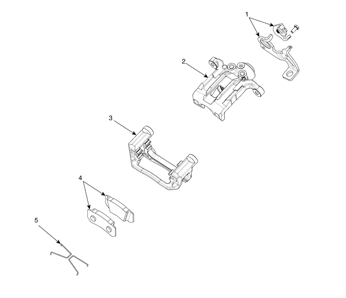
| 1. Cable cuide & Lever 2. Caliper body 3. Torque member |
4. Brake pad 5. Return spring |
Repair procedures
| Removal |
Disc
| 1. |
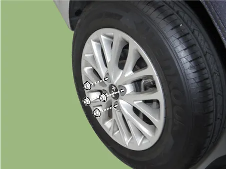
Remove the rear wheel & tire.
|
| 2. |
Release the parking brake lever and parking brake cable is loose. |
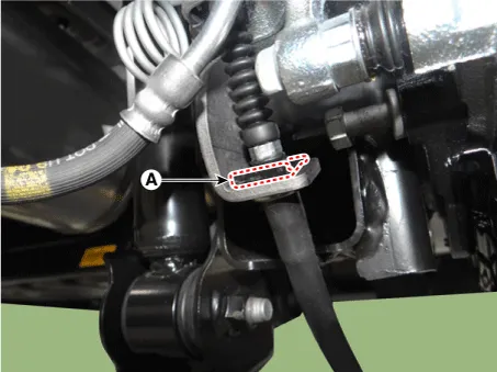
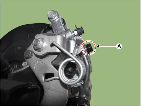
| 3. |
Remove the parking brake cable (A), after removing the clip (B).
|
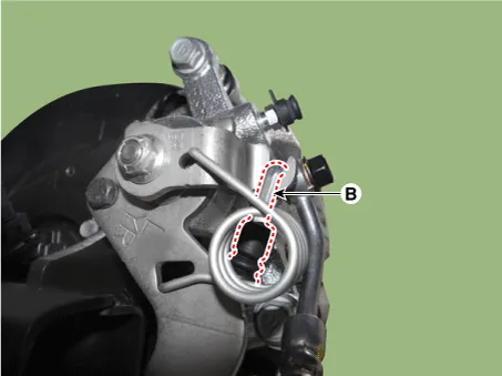
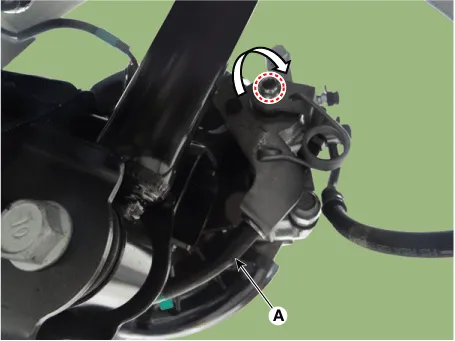
| 4. |
Pull the spanner as a below arrow in order to loosen the cable and then remove the parking cable (A).
|
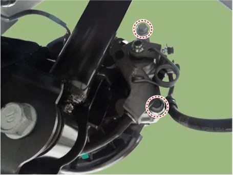
| 5. |
Remove the hose eyebolt (A).
|
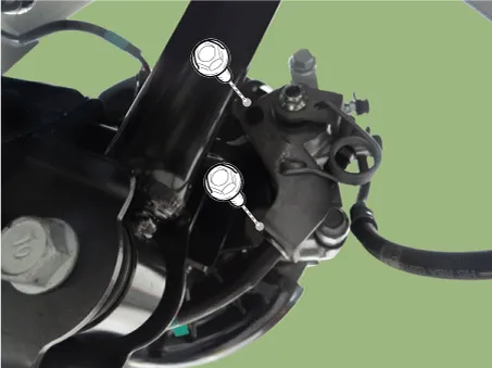
| 6. |
Loosen the caliper mounting bolts and then remove the rear caliper assembly.
|
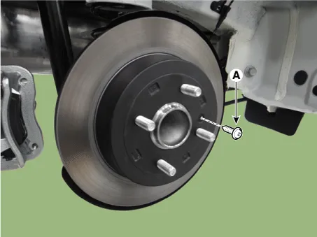
| 7. |
Loosen the rear disc screw (A) and then remove the rear disc.
|
Brake Pad
| 1. |
Remove the rear wheel & tire.
|
| 2. |
Loosen the caliper mounting bolts and then remove the rear caliper assembly.
|
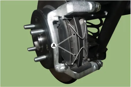
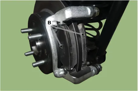
| 3. |
Remove the pad return spring (A) and then separate the brake pad (B).
|

| Inspection |
Rear Brake Disc Thickness Check
| 1. |
Check the brake pads for wear and fade. |
| 2. |
Check the brake disc for damage and cracks. |
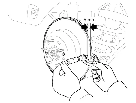
| 3. |
Remove all rust and contamination from the surface, and measure the disc thickness at 8 points, at least, at the same distance apart (5mm) from the brake disc outer circle.
|
| 4. |
If wear exceeds the limit, swab left and right discs and pad assemblies of the vehicle. |
Rear Brake Pad Check
| 1. |
Check the pad wear. Measure the pad thickness and replace it, if it is less than the specified value.
|
| 2. |
Check that grease is applied to sliding contact points and check the pad and backing metal for damage. |
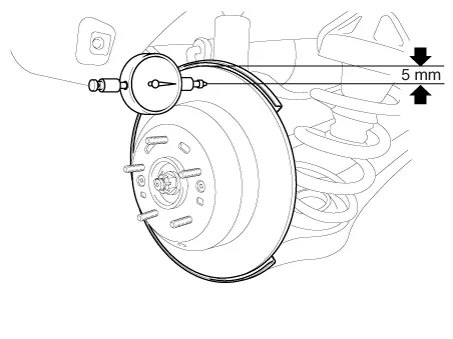
Rear Brake Disc Runout Check
| 1. |
Place a dial gauge about 5mm (0.2 in.) from the outer circumference of the brake disc, and measure the runout of the disc.
|
| 2. |
If the runout of the brake disc exceeds the limit specification, replace the disc, and then measure the runout again. |
| 3. |
If the runout does not exceed the limit specification, install the brake disc after turning it 180° and then check the brake disc again for runout. |
| 4. |
If the runout cannot be corrected by changing the position of the brake disc, replace the brake disc. |
| Installation |
| 1. |
Install in the reverse order of removal. |
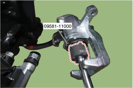
| 2. |
Use the SST (09581-11000) when installing the brake caliper assembly.
|
| 3. |
After installation, bleed the brake system. (Refer to Brake system - "Brake System") |
Components and components location Components 1. Caliper body 2. Caliper carrier 3. Brake pad assembly [IN] 4.
Components and components location Components 1. Shoe hold down pin 2. Shoe adjuster 3. Upper return spring 4. Adjusting lever 5.
Other information:
Kia Rio 2017-2023 YB Service Manual: Windshield Wiper/Washer
Components and components location Component Location 1. Windshield wiper arm & blade 2. Wiper & washer switch 3. Windshield washer hose & nozzle 4. Wiper motor & linkage assembly 5. Washer motor 6.
Kia Rio 2017-2023 YB Service Manual: Rain Sensor
Components and components location Components Schematic diagrams Circuit Diagram Description and operation Description Integrated Rain Sensor Integrated rain sensor (A) controls three systems: front wiper, auto-light, and central air conditioner.
Categories
- Manuals Home
- Kia Rio Owners Manual
- Kia Rio Service Manual
- Motor Driven Power Steering
- Cooling System
- General Information
- New on site
- Most important about car
