Kia Rio: Brake System / Brake Line
Components and components location
| Components |

Repair procedures
| Removal |
| 1. |
Disconnect the brake fluid level switch connector (A) and then remove the reservoir cap.
|

| 2. |
Remove the front/rear wheel & tire.
|

| 3. |
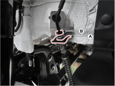
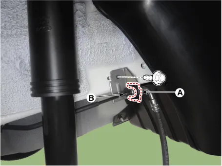
Remove the brake hose clip (A). |
| 4. |
Disconnect the brake tube by loosening the tube flare nut (B).
|
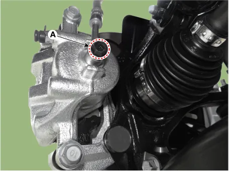
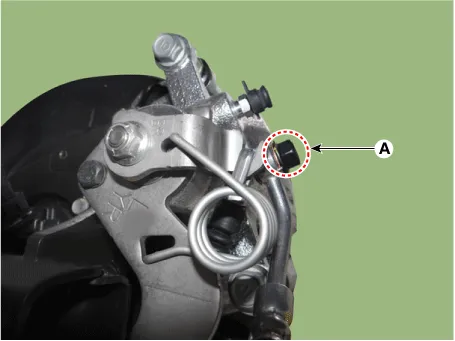
| 5. |
Disconnect the brake hose from the brake caliper by loosening the bolt (A).
|
| Inspection |
| 1. |
Check the brake tubes for cracks, crimps and corrosion. |
| 2. |
Check the brake hoses for cracks, damage and fluid leakage. |
| 3. |
Check the brake tube flare nuts for damage and fluid leakage. |
| 4. |
Check brake hose mounting bracket for crack or deformation. |
| Installation |
| 1. |
Install in the reverse order of removal.
|


| 2. |
After installation, bleed the brake system. (Refer to Brake system - "Brake System") |
| 3. |
Check the spilled brake oil. |
Components and components location Components 1. Brake booster assembly 2. Reservoir 3. Master cylinder Repair procedures Removal 1.
Components and components location Components 1. Brake member assembly 2. Stop lamp switch 3. Pedal assembly Repair procedures Removal 1.
Other information:
Kia Rio 2017-2023 YB Service Manual: Turn Signal Lamp
Repair procedures Removal Door Mirror Turn Signal Lamp 1. Disconnect the negative (-) battery terminal. 2. Remove the mirror (A) from the mirror holder. Be careful not to damag
Kia Rio 2017-2023 YB Service Manual: Heating,Ventilation, Air Conditioning
Specifications Specification Air Conditioner Item Specification Compressor Type DVE12 Oil type & Capacity PAG 30, 120 ± 10 g Displacement 122 cc/rev Expansion valve Type
Categories
- Manuals Home
- Kia Rio Owners Manual
- Kia Rio Service Manual
- Engine Control / Fuel System
- Clutch System
- Body Electrical System
- New on site
- Most important about car
