Kia Rio: Brake System / Master Cylinder
Components and components location
| Components |
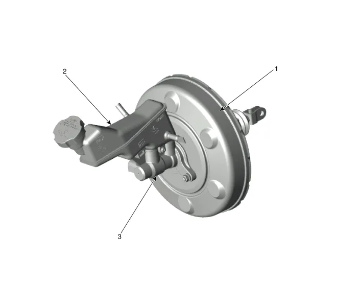
| 1. Brake booster assembly 2. Reservoir |
3. Master cylinder |
Repair procedures
| Removal |
| 1. |
Remove the battery and battery tray. D 1.4 U2 TCI (Refer to Engine Electrical System - "Battery") G 1.0 T-GDI (Refer to Engine Electrical System - "Battery") G 1.2 MPI (Refer to Engine Electrical System - "Battery") G 1.4 MPI (Refer to Engine Electrical System - "Battery") |
| 2. |
Remove the air cleaner assembly. D 1.4 U2 TCI (Refer to Engine Mechanical System - "Air cleaner") G 1.0 T-GDI (Refer to Engine Mechanical System - "Air cleaner") G 1.2 MPI (Refer to Engine Mechanical System - "Air cleaner") G 1.4 MPI (Refer to Engine Mechanical System - "Air cleaner") |
| 3. |
Remove the brake fluid from the master cylinder reservoir with a syringe.
|

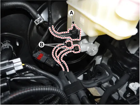
| 4. |
Disconnect the brake fluid level switch connector (A), and disconnect the brake tube (B) from the master cylinder by loosening the tube flare nut.
|
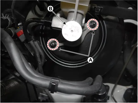
| 5. |
Remove the master cylinder (B) from the brake booster after loosening the mounting nuts (A).
|
| Installation |
| 1. |
Install in the reverse order of removal. |
| 2. |
After installation, bleed the brake system. (Refer to Brake system - "Brake System") |
Components and components location Components 1. Brake booster assembly 2. Reservoir 3. Master cylinder Repair procedures Brake Booster Operating Test For simple checking of the brake booster operation, carry out the following tests.
Components and components location Components Repair procedures Removal 1. Disconnect the brake fluid level switch connector (A) and then remove the reservoir cap.
Other information:
Kia Rio 2017-2023 YB Service Manual: Parking Assist Sensor
Components and components location Components Repair procedures Removal 1. Disconnect the negative (-) battery terminal. 2. Remove the rear bumper assembly. (Refer to Body - "Rear Bumper Assembly") 3.
Kia Rio 2017-2023 YB Service Manual: Rain Sensor
Components and components location Components Schematic diagrams Circuit Diagram Description and operation Description Integrated Rain Sensor Integrated rain sensor (A) controls three systems: front wiper, auto-light, and central air conditioner.
Categories
- Manuals Home
- Kia Rio Owners Manual
- Kia Rio Service Manual
- Engine Mechanical System
- Engine Electrical System
- Steering System
- New on site
- Most important about car
