Kia Rio: Automatic Transaxle Control System / Inhibitor Switch
Description and operation
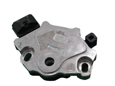
| Description |
Detect the position of shift lever through the contact switch.
Operation Table

Schematic diagrams
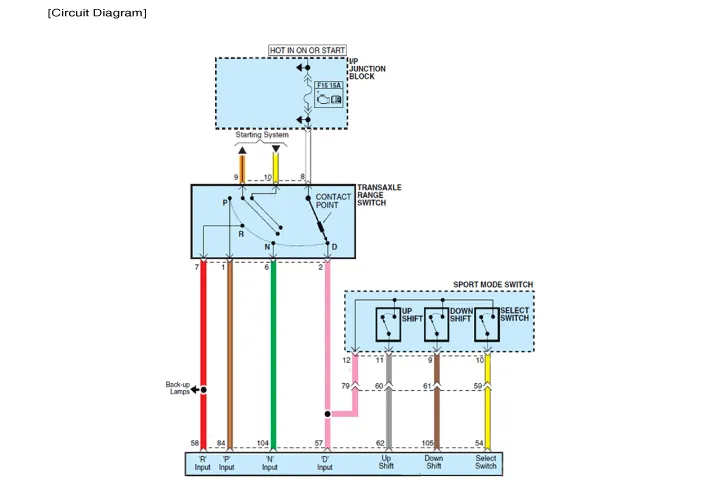
| Circuit Diagram |
Repair procedures
| Inspection |
| 1. |
Check the condition of connector.
|
| 2. |
Check the inhibitor switch circuit signal.
|
| Removal |
| 1. |
Shift the gear to "N". |
| 2. |
Remove the air cleaner. (Refer to Engine Mechanical System - "Air cleaner") |
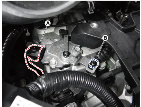
| 3. |
Disconnect the inhibitor switch connector (A) and loosen the shift cable mounting nut (B).
|
| 4. |
Remove the inhibitor switch (B) after removing the manual control lever (A).
|

| Installation |
| 1. |
Check that the gear is shifted to "N". |
| 2. |
Install the manual control lever (A) after installing the inhibitor switch (B).
|

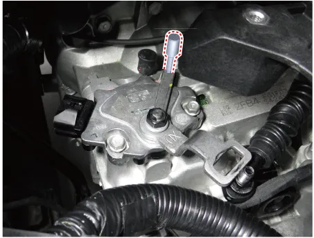
| 3. |
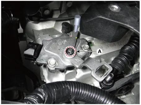
Align the hole in the manual control lever with the "N" position hole of the inhibitor switch and then insert the SST (09480-A3800).
|
| 4. |
Tighten the manual control lever mounting nut (A).
|
| 5. |
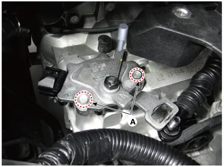
Tighten the inhibitor switch mounting bolts (A).
|
| 6. |
Remove the SST (09480-A3800).
|
| 7. |
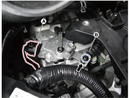
Connect the inhibitor switch connector (A). |
| 8. |
Tighten the nut (B) to the specified torque after removing free play by pushing the shift cable in the direction of the arrow
|
| 9. |
Install the air cleaner. (Refer to Engine Mechanical System - "Air cleaner") |
Specifications Specification Item Specification Type Hall effect sensor Current 22 mA (Max) Output voltage High : 4.
Components and components location Components 1. Shift lever knob & boots 2. Shift lever assembly 3. Shift cable assembly Repair procedures Removal 1.
Other information:
Kia Rio 2017-2023 YB Service Manual: Compressor
Description and operation Description The compressor is the power unit of the A/C system. It is located on the side of engine block and driven by a V-belt of engine. The compressor changes the low pressure and low temperature refrigerant gas into the high pressure and high temperature refrigerant gas.
Kia Rio 2017-2023 YB Service Manual: Condenser
Repair procedures Inspection 1. Check the condenser fins for clogging and damage. If clogged, clean them with water, and blow them with compressed air. If bent, gently bend them using a screwdriver or pliers. 2.
Categories
- Manuals Home
- Kia Rio Owners Manual
- Kia Rio Service Manual
- General Information
- Heating,Ventilation, Air Conditioning
- Engine Electrical System
- New on site
- Most important about car
