Kia Rio: Controller / Heater & A/C Control Unit (MANUAL)
Components and components location
| Components |
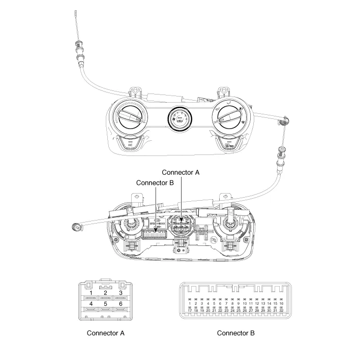
Connector pin function
|
NO. |
Connector A |
Connector B |
|
1 |
Low |
Battery |
|
2 |
Common |
ISG Battery |
|
3 |
High |
Illumination (+) |
|
4 |
Middle_LOW |
Sensor (+5V) |
|
5 |
Middle_High |
⁻ |
|
6 |
High |
Intake actuator Feedback |
|
7 |
|
Evaporator sensor (+) |
|
8 |
Ambient sensor (+) |
|
|
9 |
⁻ |
|
|
10 |
⁻ |
|
|
11 |
Intake actuator (FRE) |
|
|
12 |
Intake actuator (REC) |
|
|
13 |
HTD |
|
|
14 |
Rear defog switch |
|
|
15 |
Blower on signal to common |
|
|
16 |
Illumination (-) |
|
|
17 |
IGN2 |
|
|
18 |
IGN1 |
|
|
19 |
⁻ |
|
|
20 |
Max blower on signal |
|
|
21 |
PTC relay 3 |
|
|
22 |
PTC relay 2 |
|
|
23 |
PTC on signal |
|
|
24 |
Detent out (-) |
|
|
25 |
⁻ |
|
|
26 |
Chassis_CAN (High) |
|
|
27 |
Chassis_CAN (Low) |
|
|
28 |
⁻ |
|
|
29 |
ECV (+) |
|
|
30 |
ECV (-) |
|
|
31 |
Sensor ground |
|
|
32 |
Ground |
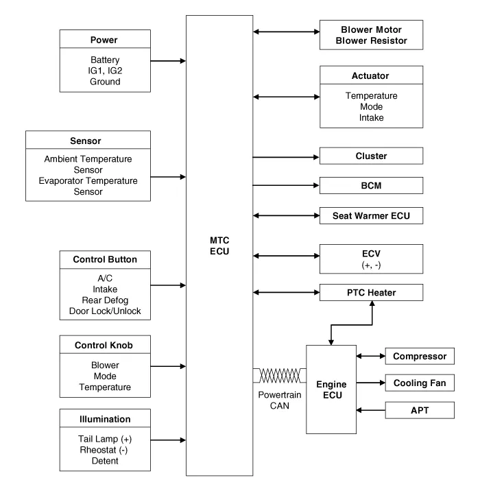
Schematic diagrams
| Schematic Diagram |
Repair procedures
| Replacement |
| 1. |
Disconnect the negative (-) battery terminal. |
| 2. |
Remove the crash pad lower panel. (Refer to Body - "Crash Pad Lower Panel") |
| 3. |
Remove the audio unit. (Refer to Body Electrical System - "Audio Unit") |
| 4. |
Remove the glove box. (Refer to Crash Pad - "Glove Box Housing") |
| 5. |
Remove the driver's side shower duct (A) after loosening the screw.
|
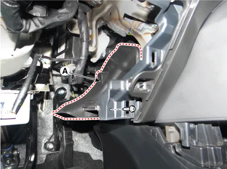
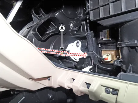
| 6. |
Disconnect the mode control cable (A).
|
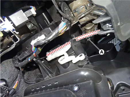
| 7. |
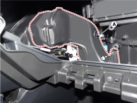
Remove the passenger's side shower duct (A) after loosening the screw.
|
| 8. |
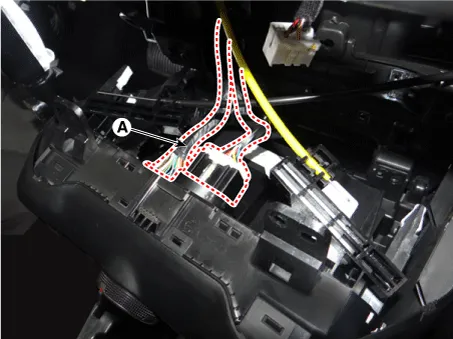
Disconnect the temperature control cable (A).
|
| 9. |
After loosening the mounting screws, remove the A/C & heater controller unit (A).
|
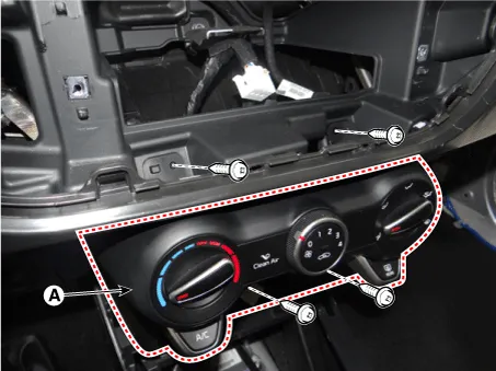
| 10. |
Disconnect the A/C & heater controller connectors (A).
|
| 11. |
To install, reverse the removal procedure. |
Components and components location Components Connector Pin Function No. Connector A Connector B 1 Battery ⁻ 2 ISG battery (+) ⁻ 3 Illumination (+) ⁻ 4 Sensor (REF) (+) Defogging actuator Feedback 5 Mode control actuator Feedback Defogging actuator (Open) 6 Temperature control actuator Feedback Defogging actuator (Close) 7 Intake actuator Feedback ⁻ 8 Evapoerator sensor (+) ⁻ 9 Ambient sensor (+) ⁻ 10 Mode control actuator (VENT) ⁻ 11 Mode control actuator (DEF) Defog current 12 Temperature control actuator (COOL) Defog temperature 13 Temperature control actuator (WARM) Defog sck 14 Intake actuator (FRE) Defog data 15 Intake actuator (REC) ⁻ 16 HTD Ground 17 Rear defog switch 18 ⁻ 19 ⁻ 20 Illumination (-) 21 IGN2 22 IGN1 23 Blower motor (+) 24 Photo sensor (-) 25 ⁻ 26 ⁻ 27 ⁻ 28 PTC relay 3 29 PTC relay 2 30 PTC on signal 31 Detent out (-) 32 ⁻ 33 Chassis_CAN (High) 34 Chassis_CAN (Low) 35 FET (Drain hose Feedback) 36 FET (Gate) 37 ECV (+) 38 ECV (-) 39 Sensor ground 40 Ground Schematic diagrams Schematic Diagrams Repair procedures Self Diagnosis 1.
Other information:
Kia Rio 2017-2023 YB Service Manual: Overhead Console Lamp
Repair procedures Inspection 1. Remove the overhead console lamp assembly then check for continuity between terminals. If the continuity is not as specified, replace the map lamp switch. Removal 1.
Kia Rio 2017-2023 YB Service Manual: Power Door Lock Switch
Repair procedures Removal • When removing with a flat-tip screwdriver or remover, wrap protective tape around the tools to prevent damage to components.
Categories
- Manuals Home
- Kia Rio Owners Manual
- Kia Rio Service Manual
- Timing Chain
- Emission Control System
- Body Electrical System
- New on site
- Most important about car
