Kia Rio: Air Conditioning System / Compressor
Description and operation
| Description |
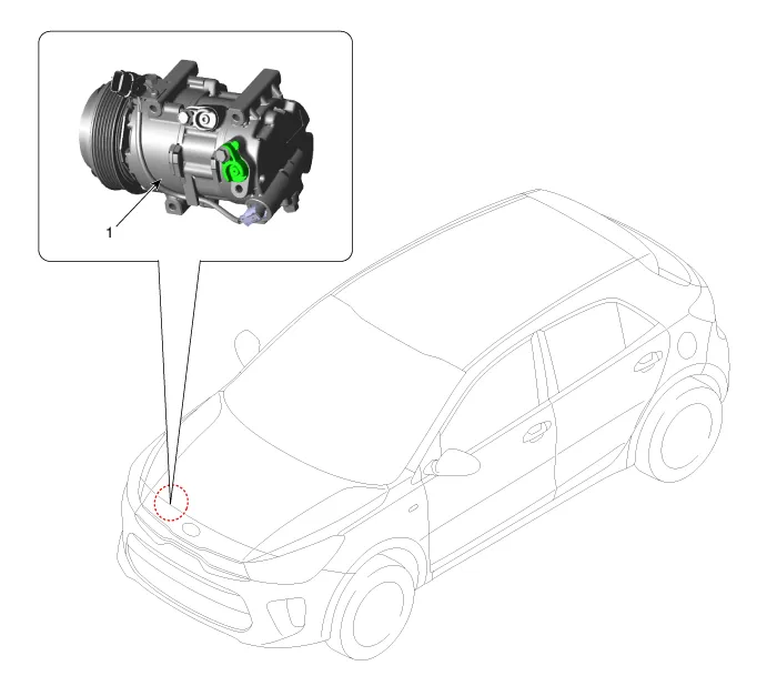
The compressor is the power unit of the A/C system.
It is located on the side of engine block and driven by a V-belt of engine.
The compressor changes the low pressure and low temperature refrigerant gas into the high pressure and high temperature refrigerant gas.
Variable Swash Plate Compressor
The compressor has a swash plate that rotates to reciprocate pistons, which compress refrigerant.
The variable swash plate compressor controls the swash plate angle to change the refrigerant displacement. It achieves precise cooling capability control in accordance with vehicle interior and driving conditions.
The internally controlled variable swash plate compressor changes the swash plate angle by a MCV (Mechanical Control Valve) in accordance with fluctuation of a suction pressure.
The externally controlled variable swash plate compressor changes the swash plate angle by an ECV (Electric Control Valve) in accordance with an electrical signal from the heater & A/C control unit.
This enables stable temperature control and improved driving feeling.
ECV control diagram

Components and components location
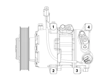
| Components |
| Compressor
|
Repair procedures
| Removal |
| 1. |
If the compressor is marginally operable, run the engine at idle speed, and let the air conditioning work for a few minutes, then shut the engine off. |
| 2. |
Disconnect the negative cable from the battery. |
| 3. |
Recover the refrigerant with a recovery/charging station. |
| 4. |
Remove the front tire [RH]. (Refer to Suspension System - "Wheel") |
| 5. |
Remove the front wheel guard [RH]. |
| 6. |
Loosen the drive belt. D 1.4 TCI-U2(Refer to Engine Mechanical System - "Drive Belt") G 1.0 T-GDI-KAPPA(Refer to Engine Mechanical System - "Drive Belt") G 1.2 MPI-KAPPA(Refer to Engine Mechanical System - "Drive Belt") G 1.4 MPI-KAPPA(Refer to Engine Mechanical System - "Drive Belt") |
| 7. |
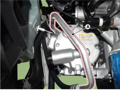
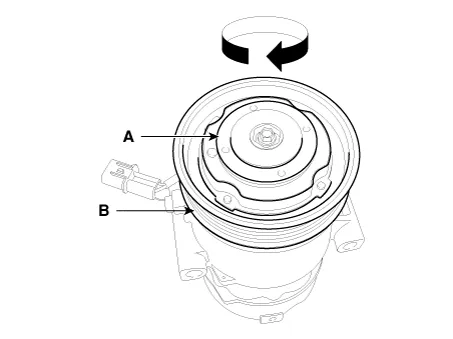
Disconnect the suction line (A) and discharge line (B) from the compressor.
|


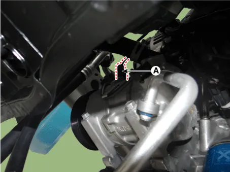
| 8. |
Disconnect the compressor switch connector (A).
|
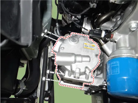
| 9. |
Remove the compressor by loosening the mounting bolts.
|
| Installation |
| 1. |
Make sure of the length of compressor mounting bolts, and then tighten it with the specified tightening order.
|
| 2. |
Installation is the reverse order of removal.
|
| Inspection |
| 1. |
Check the plated parts of the disc & hub assembly (A) for color changes, peeling or other damage. If there is damage, replace the clutch set. |
| 2. |
Check the pulley (B) bearing play and drag by rotating the pulley by hand. Replace the clutch set with a new one if it is noisy or has excessive play/drag.
|
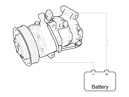
| 3. |
Check operation of the magnetic clutch. Connect the compressor side terminals to the battery (+) terminal and the ground battery (-) terminal to the compressor body. Check the magnetic clutch operating noise to determine the condition.
|
| External Control Valve Compressor Inspection (GDS) |
Compressor type: Fixed type compressor, External control valve, Internal control valve.
In cases of fixed type and internal control valve, it is possible to inspect compressor's operation with clutch noise.
When it comes to External control valve, however, it cannot be checked in this way bacause it doesn't have a clutch.
So, ECV should be inspected with GDS as below.
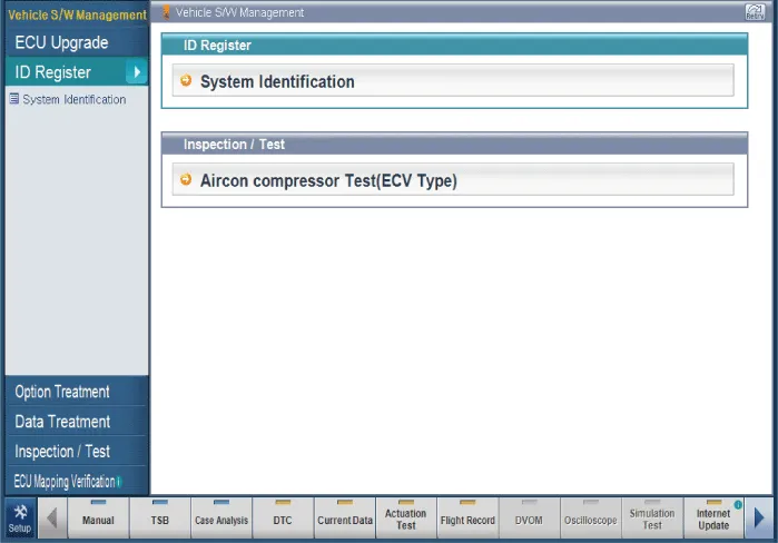
| 1. |
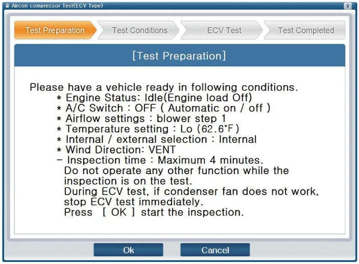
Connect GDS to the vehicle and select 'Aircon Compressor Test(ECV type)' [ECV1]
|
| 2. |
Make the vehicle ready as the GDS instruction on the monitor. (Turn off A/C 'switch' only) [ECV2]
[ECV3]
|

| 3. |
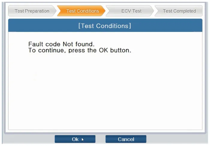
Check if other DTC codes are found before inspect ECV compressor. If so, solve that problems first. If not, press 'OK' button to continue.
[ECV4]
|

| 4. |
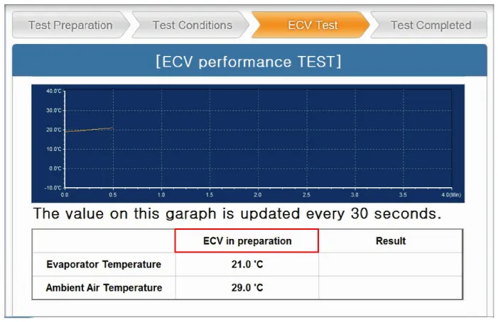
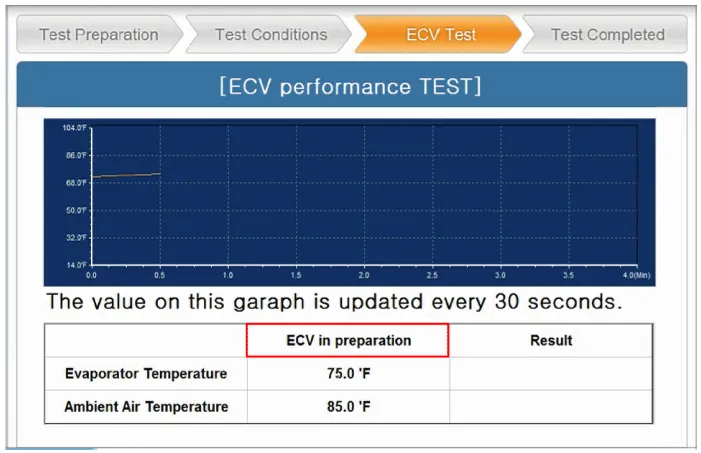
Start inspection [ECV5]
[ECV6]
|

| 5. |
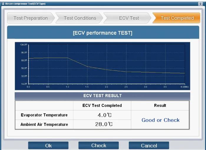
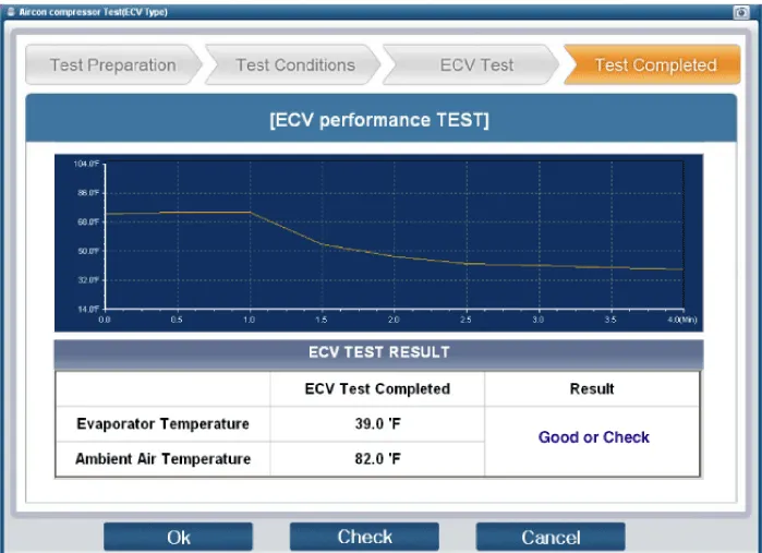
Check the result of inspection. [ECV7]
[ECV8]
|
| 6. |
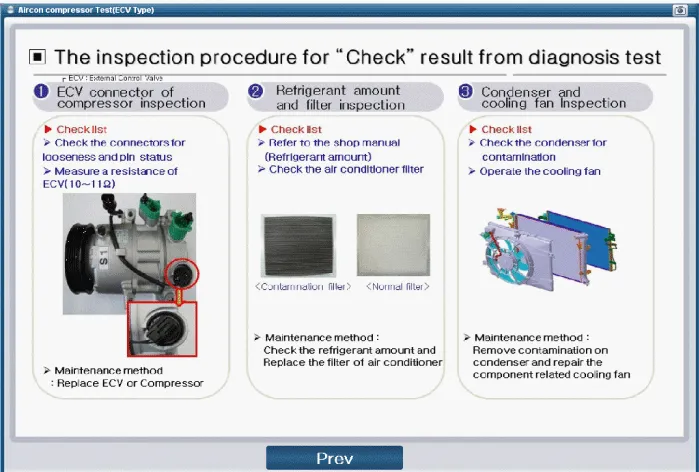
If the result shows "Check" , click "Check" and follow the instruction.
|
| 7. |
Inspect ECV again from the first step. |
| Disassembly |
| 1. |
Remove the RH front tire. (Refer to Suspension System - Wheel") |
| 2. |
Remove the front wheel guard [RH]. (Refer to Body - "Front Wheel Guard") |
| 3. |
Loosen the drive belt. D 1.4 TCI-U2(Refer to Engine Mechanical System - "Drive Belt") G 1.0 T-GDI-KAPPA(Refer to Engine Mechanical System - "Drive Belt") G 1.2 MPI-KAPPA(Refer to Engine Mechanical System - "Drive Belt") G 1.4 MPI-KAPPA(Refer to Engine Mechanical System - "Drive Belt") |
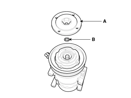
| 4. |
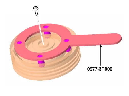
Remove the center bolt (A) and the hub bolts (B) while holding the pulley with a disc & hub assembly bolt remover (0977-3R000).
|
| 5. |
Remove the hub assembly (A) and shim (gap washer) (B), taking care not to lose the shim.
|
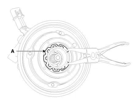
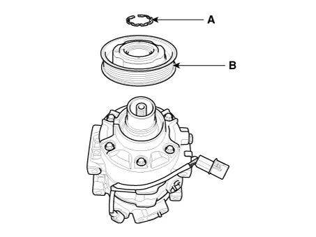
| 6. |
Remove the pulley (B) after removing the snap ring (A) with snap ring pliers.
|
| 7. |
Reassembly is the reverse order of disassembly.
|
Repair procedures Replacement 1. Discharge refrigerant from refrigeration system. 2. Replace faulty tube or hose.
Repair procedures Inspection 1. Check the condenser fins for clogging and damage. If clogged, clean them with water, and blow them with compressed air.
Other information:
Kia Rio 2017-2023 YB Service Manual: Power Window Switch
Components and components location Components Driver Power Window Switch Connector Pin Information [Front / Rear Driver Safety - Auto Up/Down] [LHD] No. Description No. Description 1 Front right power window (Up) 10
Kia Rio 2017-2023 YB Service Manual: Photo Sensor (FATC only)
Description and operation Description The photo sensor is located at the center of defrost nozzles. The photo sensor contains a photovoltaic (sensitive to sunlight) diode. The solar radiation received by its light receiving portion, generates an electromotive force in proportion to the amount of radiation received which is tran
Categories
- Manuals Home
- Kia Rio Owners Manual
- Kia Rio Service Manual
- Engine Electrical System
- Drive Belt
- Body Control Module (BCM)
- New on site
- Most important about car
