
Kia Rio: Driveshaft Assembly / BJ Boot
Components and components location
| Components |
| [RH] |
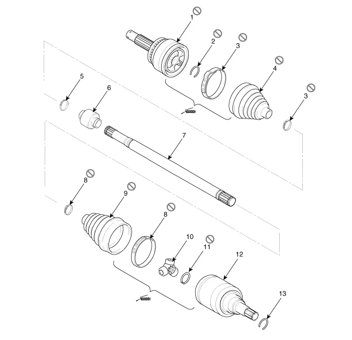
| 1. BJ assembly 2. Clip 3. BJ boot band 4. BJ boot |
5. Dynamic damper band
6. Dynamic damper 7. Shaft 8. TJ boot band |
9. TJ boot
10. Spider assembly 11. Circlip 12. TJ housing |
13. Circlip |
| [LH] |
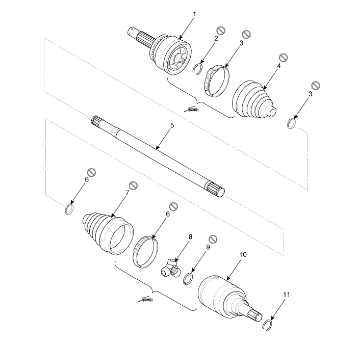
| 1. BJ assembly 2. BJ circlip 3. BJ boot band 4. BJ boot |
5. Shaft 6. TJ boot band 7. TJ boot 8. Spider assembly |
9. Snap
ring 10. TJ case 11. Circlip |
Repair procedures
| Replacement |
| 1. |
Remove the front driveshaft. (Refer to Driveshaft Assembly - “Front Driveshaft”) |
| 2. |
Remove the TJ joint assembly. (Refer to Driveshaft Assembly - “TJ Joint”) |
| 3. |
Remove the Dynamic damper. (Refer to Driveshaft Assembly - “Dynamic Damper”) |
| 4. |
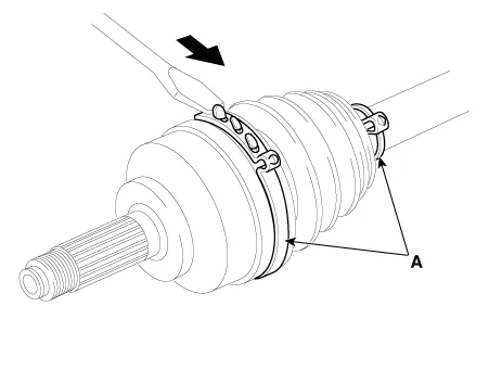
Using a plier or flat-tipped (-) screwdriver, remove the BJ boot bands (A).
|
| 5. |
Remove the BJ boot. |
| 6. |
Install in the reverse order of removal.
|

| 7. |
Check the front alignment. (Refer to Suspension System - "Alignment") |
Components and components location Components [RH] 1. BJ assembly 2. Clip 3. BJ boot band 4. BJ boot 5.
Components and components location Components [Drum Type] 1. Torsion beam axle 2. Rear spring 3. Rear drum brake disc [Disc Type] 1.
Other information:
Kia Rio 2017-2023 YB Service Manual: Indicators And Gauges
Troubleshooting Troubleshooting Error Item Failure symptom Inspection items Detailed inspections Relevant Parts/ Components Screen display LCD screen does not turn on 1) Connector attachments
Kia Rio 2017-2023 YB Service Manual: Smart Key System
Specifications Specifications Smart Key Unit Items Specification Rated voltage DC 12 V Operating voltage DC 9 - 16 V Operating temperature -31 - 167°F (-35 - 75°C) Load Max.
Categories
- Manuals Home
- Kia Rio Owners Manual
- Kia Rio Service Manual
- Suspension System
- Steering System
- Clutch System
- New on site
- Most important about car
