Kia Rio: Cylinder Block / Piston and Connecting Rod
Repair procedures
| Disassembly |
|

|

| 1. |
Remove the engine assembly from the vehicle. (Refer to Engine and Transaxle Assembly - "Engine and Transaxle Assembly”) |
| 2. |
Remove the transaxle assembly from the engine assembly. ·Manual Transaxle (Refer to Manual Transaxle System - "Manual Transaxle") ·Automatic Transaxle (Refer to Automatic Transaxle System - "Automatic Transaxle") |
| 3. |
Remove the drive plate or flywheel. ·Automatic Transaxle (Refer to Cylinder Block Assembly - "Drive Plate") ·Manual Transaxle (Refer to Cylinder Block Assembly - "Flywheel") |
| 4. |
Install the engine to engine stand for disassembly. |
| 5. |
Remove the timing chain. (Refer to Timing System - "Timing Chain”) |
| 6. |
Remove the intake manifold. (Refer to Intake and Exhaust System - "Intake Manifold") |
| 7. |
Remove the exhaust manifold. (Refer to Intake and Exhaust System - "Exhaust Manifold") |
| 8. |
Remove the cylinder head assembly. (Refer to Cylinder Head Assembly - "Cylinder Head") |
| 9. |
Remove the water pipe. (Refer to Cooling System - "Thermostat") |
| 10. |
Remove the water temperature control assembly. (Refer to Cooling System - "Thermostat") |
| 11. |
Remove the oil pan and oil screen. (Refer to Lubrication System - "Oil Pan") |
| 12. |
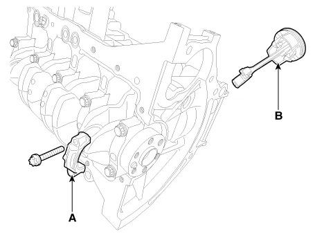
Remove the ladder frame. (Refer to Cylinder Block - "Cylinder Block") |
| 13. |
Check the connecting rod end play. |
| 14. |
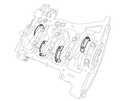
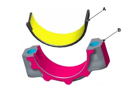
Remove the connecting rod caps and check oil clearance. |
| 15. |
Check the connecting rod cap oil clearance. |
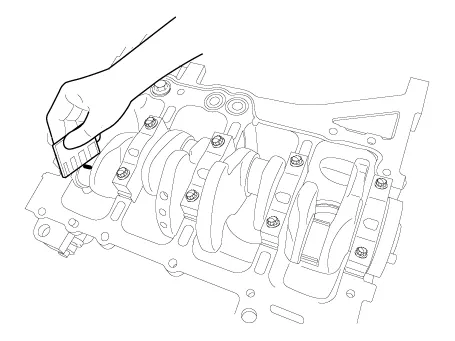
| 16. |
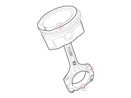
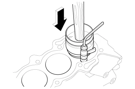
Remove the piston and connecting rod assemblies.
|
| 17. |
Check fit between piston and piston pin. Try to move the piston back and forth on the piston pin. If any movement is felt, replace piston and piston pin as a set. |
| 18. |
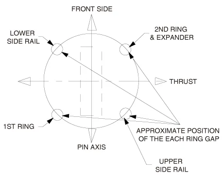
Remove the piston rings.
|
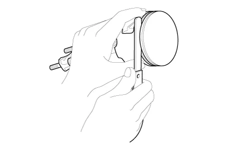
| 19. |
Remove the connecting rod from the piston. Using a press, remove the piston pin from the piston.
|
| Inspection |
Connecting Rod
| 1. |
Check the connecting rod end play. Using a feeler gauge, measure the end play while moving the connecting rod back and forth.
|

| 2. |
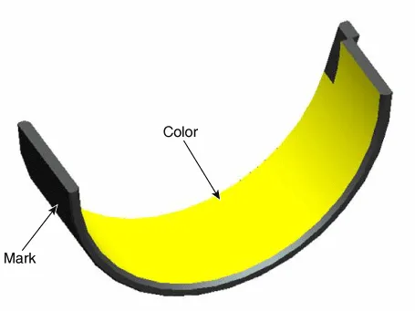
Check the connecting rod bearing oil clearance.
|
|||||||||||||||||||||||||||||||||||||||||||||||||||||||||||||||||||||||||||||||||||||||||||||||||||||||||||
Piston
| 1. |
Clean the piston
|
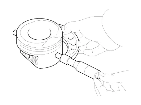
| 2. |
The standard measurement of the piston outside diameter is taken 30.0mm (1.21in) from top land of the piston.
|
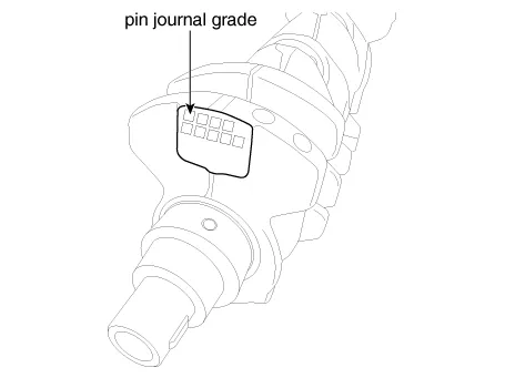
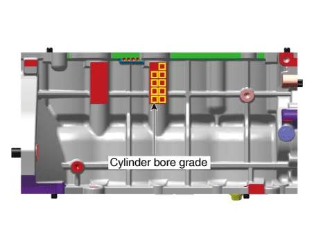
| 3. |
Check the cylinder bore size code on the cylinder block.
Discrimination of cylinder bore size
|
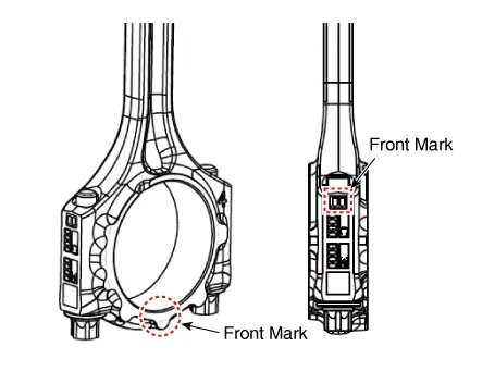
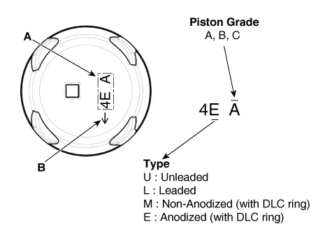
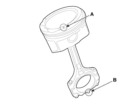
| 4. |
Check the piston size code (A) and the front mark (B) on the piston top face.
Discrimination Of Piston Outer Diameter
|
| 5. |
Select the piston related to cylinder bore class.
|
Piston Rings
| 1. |
Calculate the difference between the cylinder bore diameter and the piston diameter.
|
| 2. |
Inspect the piston ring side clearance. Using a feeler gauge, measure the clearance between new piston ring and the wall of the ring groove.
If the clearance is greater than maximum, replace the piston. |
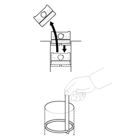
| 3. |
Inspect piston ring end gap. To measure the piston ring end gap, insert a piston ring into the cylinder bore. Position the ring at right angles to the cylinder wall by gently pressing it down with a piston. Measure the gap with a feeler gauge. If the gap exceeds the service limit, replace the piston ring. If the gap is too large, recheck the cylinder bore diameter against the wear limits. If the bore is over the service limit, the cylinder block must be replaced.
|
Piston Pins
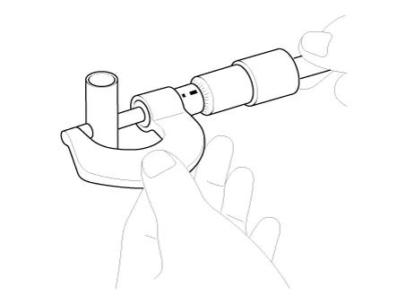
| 1. |
Measure the diameter of the piston pin.
|
| 2. |
Measure the piston pin-to-piston clearance.
|
| 3. |
Check the difference between the piston pin outer diameter and the connecting rod small end inner diameter.
|
| Reassembly |
|
| 1. |
Assemble the piston and connecting rod.
|
| 2. |
Install the piston rings.
|
| 3. |
Install the connecting rod bearings.
|
| 4. |
Install the piston and connecting rod assemblies.
|
| 5. |
Check the connecting rod end play. |
| 6. |
Assemble the other parts in the reverse order of disassembly. |
Repair procedures Replacement 1. Remove the transaxle assembly. (Refer to Manual Transaxle System - "Manual Transaxle") (Refer to Automatic Transaxle System - "Automatic Transaxle") 2.
Repair procedures Disassembly • Use fender covers to avoid damaging painted surfaces.
Other information:
Kia Rio 2017-2023 YB Service Manual: Power Door Mirrors
C
Kia Rio 2017-2023 YB Service Manual: Heater & A/C Control Unit (MANUAL)
Components and components location Components Connector pin function NO. Connector A Connector B 1 Low Battery 2 Common ISG Battery 3 High Illumination (+)
Categories
- Manuals Home
- Kia Rio Owners Manual
- Kia Rio Service Manual
- Brake System
- Coolant
- Drive Belt
- New on site
- Most important about car
